UNLOADING
After receiving your CINCINNATI FM Hydraulic
Press Brake, carefully remove the contents of the
one or more boxes shipped with the machine. In
these boxes are all of the machine’s optional acces-
sories and small parts, such as wrenches and lev-
eling shims. Check all of the parts in the boxes with
the packing list. Claims for shortages should be
made within ten days.
Leave the shipping skids attached to the machine
until it has been moved to its final location.
The 400FM through 14' machines are typically
shipped assembled on skids. The bed is mounted
on the back of the housings. Due to weight or
height limitations, longer machines or machines
with special main members, are typically shipped
disassembled.
400FM x 16' and larger machines are typically
shipped disassembled. Each of the five main mem-
bers can be handled by a crane of sufficient
capacity with chains or cables of adequate size
(refer to American National Standards Institute
B30.9). Shipping weights of the five members
(right housing, left housing, bed, ram and housing
brace) are clearly listed on the Bill of Lading for
the shipment. Check these weights carefully
before lifting or handling.
LIFTING AND MOVING
CINCINNATI INCORPORATED recommends that
professional riggers be employed to handle the
machine. They are experienced in safe handling
and will minimize risk of damage to the machine.
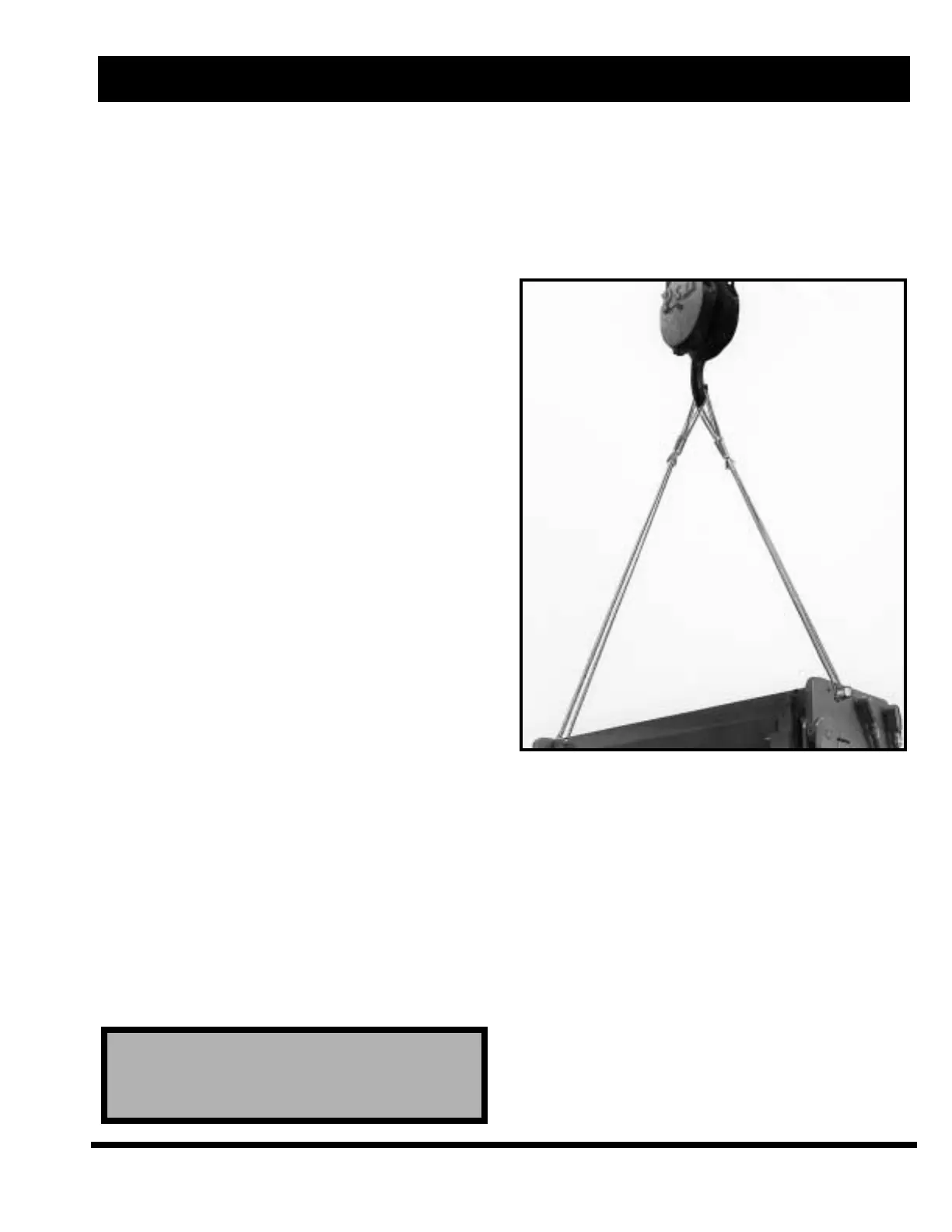
The assembled machines can be handled by cranes
of sufficient capacity. Use chains or cables adjust-
ed to the proper length for even lifting. The chains
or cables should be long enough to minimize the
side loading on the housings. If short cables are
used, fit a spreader beam between the housings
near the lifting holes. A typical hitch is shown in
Figure 2-1.
Where your crane does not have sufficient capacity,
or no crane is available, rig the machine into final
location. When rigging assembled machines into
position, leave the bed attached to the back of the
housing. If jacks are used to lower the press brake
onto the foundation bolts, care should be taken to
prevent twisting of the machine.
FIGURE 2-1 – Lifting the machine
Disassembled machines can be lifted directly from
the vehicle if crane capacities are sufficient. The
right and left housings should be lifted by the
lifter hole as shown in Figure 2-2. If a clevis as
shown is not available, an adequate strength cable
should be used in the same housing hole. The bed
and ram should be lifted with a cable through the
large lifting holes. Be sure to protect finished sur-
faces from damage.
Where crane capacities are not sufficient or avail-
able, the five main members can be handled by
using jacks, roller bars and a mobile crane. Care
should be taken to prevent damage to finished
surfaces and parts attached to main members of
the machine.
! W
! W
ARNING !
ARNING !
BE EXTREMELY CAREFUL TO KEEP MACHINE
SUPPORTED EVENLY AND TO GUARD AGAINST
TIPPING.
EM-446 (N-08/99)
2-1
SECTION 2 INSTALLATION