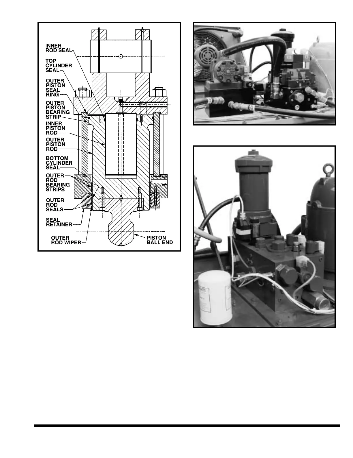
FIGURE 9-8 – Cylinder assembly
MOTOR / PUMP
The motor/pump combination(s) is vertically
mounted on the reservoir top with the pump(s)
submerged in the hydraulic oil. The pump(s) is a
variable volume, pressure compensated piston
pump(s) with a load sensor control. The compen-
sating and load sensor pressures are factory set
and no adjustments are required.
VALVES
The hydraulic control valves are manifold mounted
on the reservoir (
Figure 9-9A and 9-9B) and on both
cylinders (Figure 9-7). The valves can be easily
removed for service or replacement.
FIGURE 9-9A – Manifold mounted control valves
(For 400 - 750 FM Standard)
FIGURE 9-9B – Manifold mounted control valves
(For Hydraulic Speed Package & 1000 - 2000 FM)
IMPORTANT: Whenever servicing these valves,
the ram should be blocked, all power to the
machine turned OFF and the electrical dis-
connect off and locked.
SWIVEL END-GUIDE BEARING
The swivel end-guide bearing provides the adjust-
ment for side clearance of the slides and guides. To
adjust the end-guide clearance:
9-7