necessary to obtain the proper flange dimen-
sion, enter the positive or negative value in
this field. A negative value moves the back-
gage toward the tooling. A positive value
moves the backgage away from the tooling.
The bend allowance can also be used as a
“finger offset” to compensate for non-standard
gage finger lengths or for gaging on the shelf
of a .25” finger.
Valid Range: -0.999 - +0.999
Entry Format: 0.XXX English or X.XX Metric
Default Value: 0.000
GA. PAUSE (Gage Pause): This value repre-
sents the amount of time in seconds the back-
gage will delay at the current step position or
retracted position before advancing to the next
step programmed position. The pause timer
starts after the ram returns to the top of
stroke. When a gage pause time is non-zero,
the gage will not move forward (towards the
dies) to the next step position until the ram has
returned to the top of stroke and the gage
pause timer has expired. If the gage pause time
is programmed to zero, the gage will move
backward or forward at the bottom of the
stroke, depending on the next step pro-
grammed position.
Valid Range: 0.0 - 9.9
Entry Format: X.X
Default Value: 0.1 ==> Gage will not move to
next step until ram has returned to top of stroke
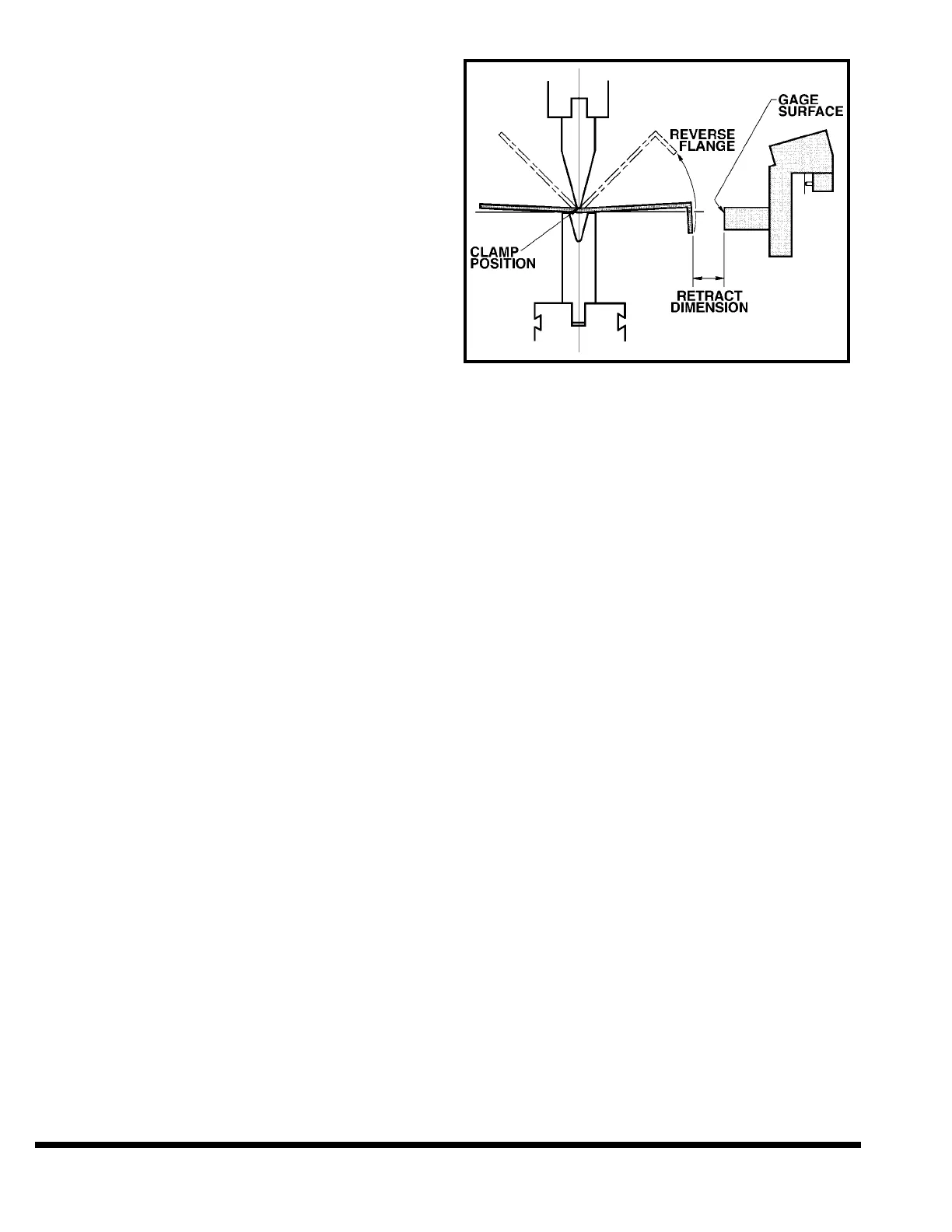
RETR DIS (Retract Distance): This value is
the distance the gage will move back from the
programmed flange dimension once the ram
has reached the clamp position (see CLAMP
POSITION). See Figure 7-5. It is used to pro-
vide clearance during the bend between the
workpiece and the gage surface when the part
has a reverse flange. If the value entered
results in a retract position greater than the
maximum gage travel then the gage will only
retract to the maximum travel without gener-
ating an error. If the ram reaches the bottom
of the stroke before the clamp position, the
gage will retract at reversal. The gage will
move to either the retract position or the next
step flange dimension, whichever is further
from the dies.
Valid Range: 0.000 - X Max Dimension
Entry Format: XX.XXX English or XXXX.XX
Metric
Default Value: 0.000
FIGURE 7-5 – Clamp and Retract
CLAMP: This function is used in conjunction
with the ram CLAMP POSITION and the gage
RETRACT DISTANCE. When the CLAMP func-
tion is ON, the control stops the ram on the
down stroke at the programmed CLAMP POSI-
TION. The operator must then release and reac-
tivate the palmbutton or footswitch to continue
the bend. If a retract distance has been pro-
grammed, the backgage will retract away from
the workpiece when the ram reaches clamp
position.
If the CLAMP function is set to PAUSE, the ram
will hesitate for a moment at the clamp position
while the gage retracts, then continue on. It is
not necessary to release and reactivate the oper-
ator controls when PAUSE is selected.
When the CLAMP function is off, the ram will not
stop at the clamp position but the gage will
retract as the ram passes the CLAMP POSITION.
To select the CLAMP function, use the arrow
keys to highlight the CLAMP field. Press the “Off”
softkey’s button to turn the clamp stop off. Press
the “On/Pause” softkey’s button to toggle
between ON and PAUSE.
FRONT PANEL SETTINGS
There are two functions on the front panel of the
control which are programmed on a per step
basis. These are the FORM SPEED SELECT and
the STROKE STOPS. The setting of these two
functions are not indicated on the display itself.
Instead the setting is indicated by an LED under
the specific function. When changing steps the
LED’s will change to reflect the programmed set-
ting for that step.
7-8