CAPACITY
The CNC Plate Gage has a 24” or 40” X-axis and an
8” or 12” R-axis. The X-axis is driven at 400
in./min., and the R-axis at 90 in./min. If large
plates or sheets weighing over 150 lbs. (68 Kg) are
to be gaged, then the CNC Plate Gage should be
used.
The CNC Heavy Duty Backgage has a 24” or 40” X-
axis and a manual or programmble 8” or 12” R-
axis. The X-axis is driven at 1200 in./min., and the
optional programmable R-axis at 300 in./min. The
CNC Heavy Duty Backgage should only be used for
sheets 1/4” (6.4mm) maximum thickness and
weigh less than 150 lbs. (68 Kg).
IMPORTANT: Reasonable care should be used
when positioning heavy material against
the gages. Heavy shock loads could dam-
age parts of the gage.
GAGE ASSEMBLY
Two gage assemblies are furnished with each back-
gage and are mounted on the backgage gage bar.
The gage assemblies (Figure 5-7) are manually
positioned along the length of the gage bar, usually
centered on the tooling and spaced apart a distance
less than the length of the workpiece.
FIGURE 5-7 – Gage assembly
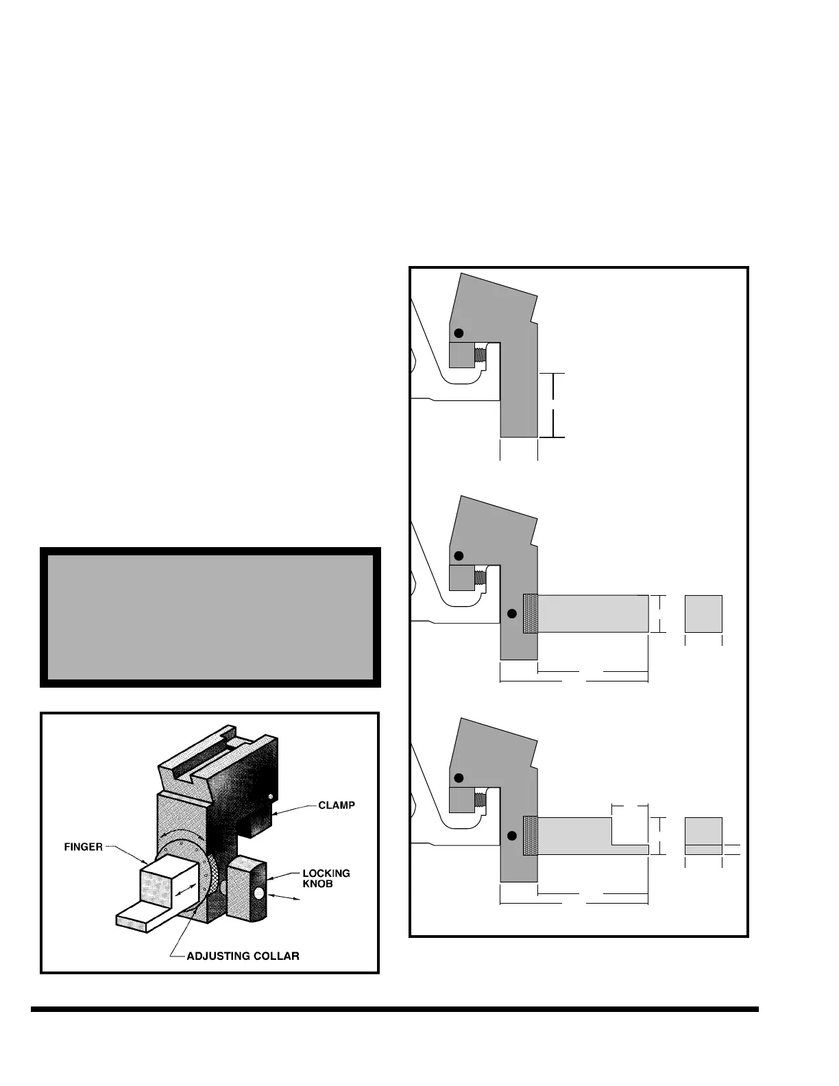
Two pairs of gage fingers are furnished with each
backgage. The 1” (25mm) gage finger or the 1/4”
(6.4mm) gage finger is installed into the gage
assembly as shown in Figure 5-8. The 1” (25mm)
gage finger should be used wherever possible, as it
provides the largest target and contact area. The
1/4” (6.4mm) gage finger can be rotated in the gage
assembly to provide either a 1” (25mm) or a 1/4”
(6.4mm) high surface for short flanges. An optional
1/8” (3.2mm) gage finger can be furnished for
smaller flanges. 1”, 1/4”, and 1/8” optional flip fin-
gers are also available.
FIGURE 5-8 – Standard gaging surfaces
STD. GAGE ASSEMBLY – 1" FINGER
STD. GAGE ASSEMBLY – 1/4" FINGER