Machine must be connected to a good earth
ground. A ground lug on the line side of the
machine main disconnect is provided for this pur-
pose. Refer to local and state codes for acceptable
grounding methods.
Note: If CINCINNATI INCORPORATED Service Rep-
resentative is not present, call before pro-
ceeding any further or starting machine.
He will complete all electrical connections and
check motor rotation.
CNC PLATE GAGE (Optional)
The CNC Plate Gage is an optional feature which
provides capability for plate forming applications.
Remove the backgage arm assemblies and gage bar
from packing boxes. Remove any protective wrap-
ping and clean the parts. Backgage arm assemblies
are identified as “LEFT HAND” or “RIGHT HAND” by
metal tags on top of the assembly. Install assem-
blies to rear dovetail slot in bed using dovetail bolts,
hex nuts and lockwashers. The “LEFT HAND”
assembly is mounted toward the left side as viewed
from the front of the machine (see Figure 2-8). Use
roll pin holes drilled at the factory to locate assem-
blies along slot. Install roll pins and tighten mount-
ing nuts securely.
Before installing gage bar, install backgage support
legs under backgage arm assemblies. Arm assem-
blies should now be leveled using leveling screws on
support legs. Place precision level on upper guide
rail and adjust screw to raise or lower rear of back-
gage arm assembly as required. Tighten leveling
screw locknuts when finished.
Install gage bar by inserting horizontal guides into
right mounting block. Mount left end of bar to
mounting plate using cap screws provided.
Do not make any electrical connections. This
will be done by a CINCINNATI INCORPORATED
Service Representative.
Clean the horizontal guide rails and lubricate by
spraying them with SAE #10 oil.
2-8
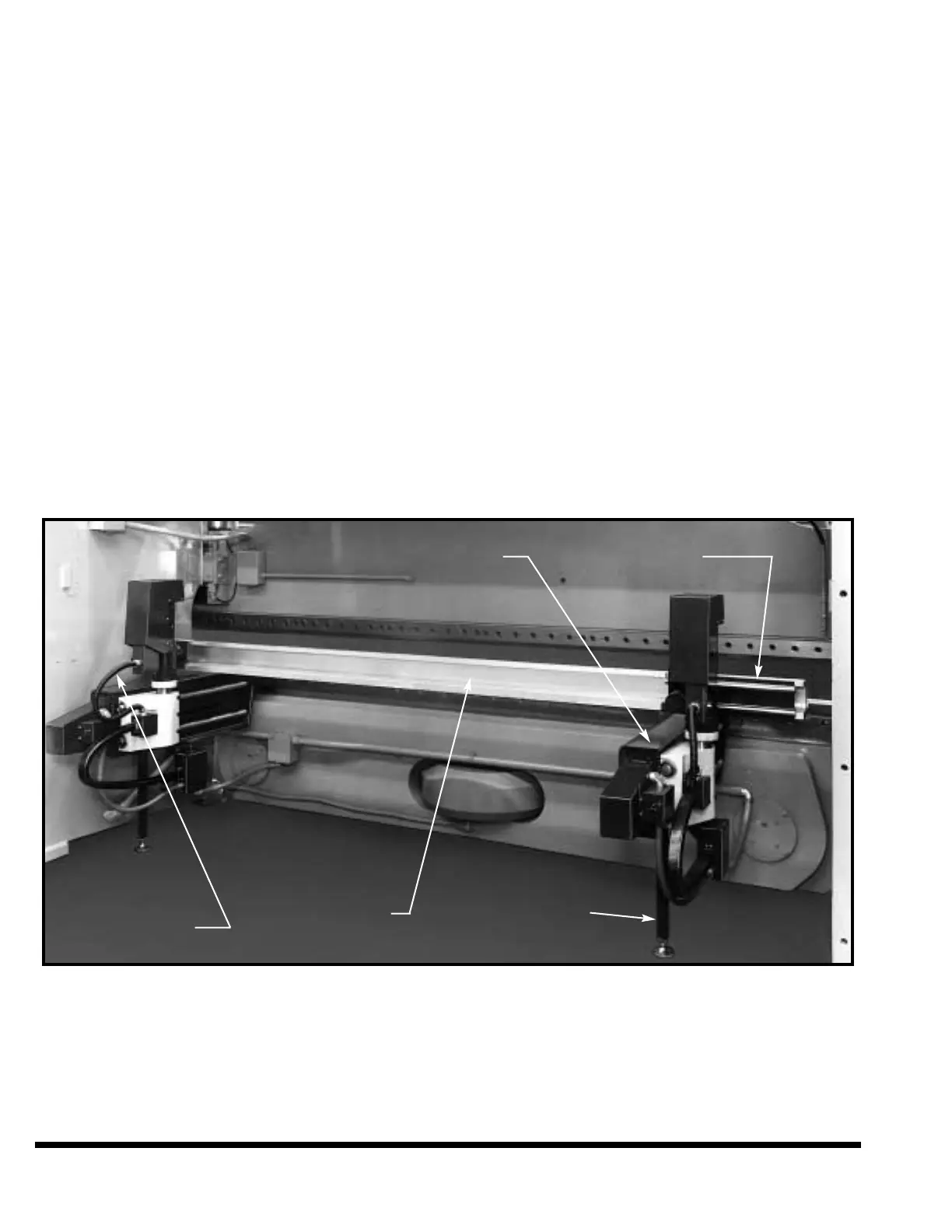
FIGURE 2-8 – CNC Plate Gage (shown with optional Auto Crown)
RIGHT ARM
ASSEMBLY
GAGE BAR SUPPORT LEG
HORIZONTAL
GUIDES
LEFT ARM
ASSEMBLY
❦