MACHINE CONTROL
STATIONS
The FM Hydraulic Press Brake uses a microcom-
puter controlled programmable system that con-
trols machine motion.
The FM Control Station is mounted on a movable
pedestal. The controls are used to set the mode of
machine operation and settings are generally
determined by the part(s) being formed and tool-
ing used. Keylock selector switches are provided
for use by supervisory or setup personnel to main-
tain settings.
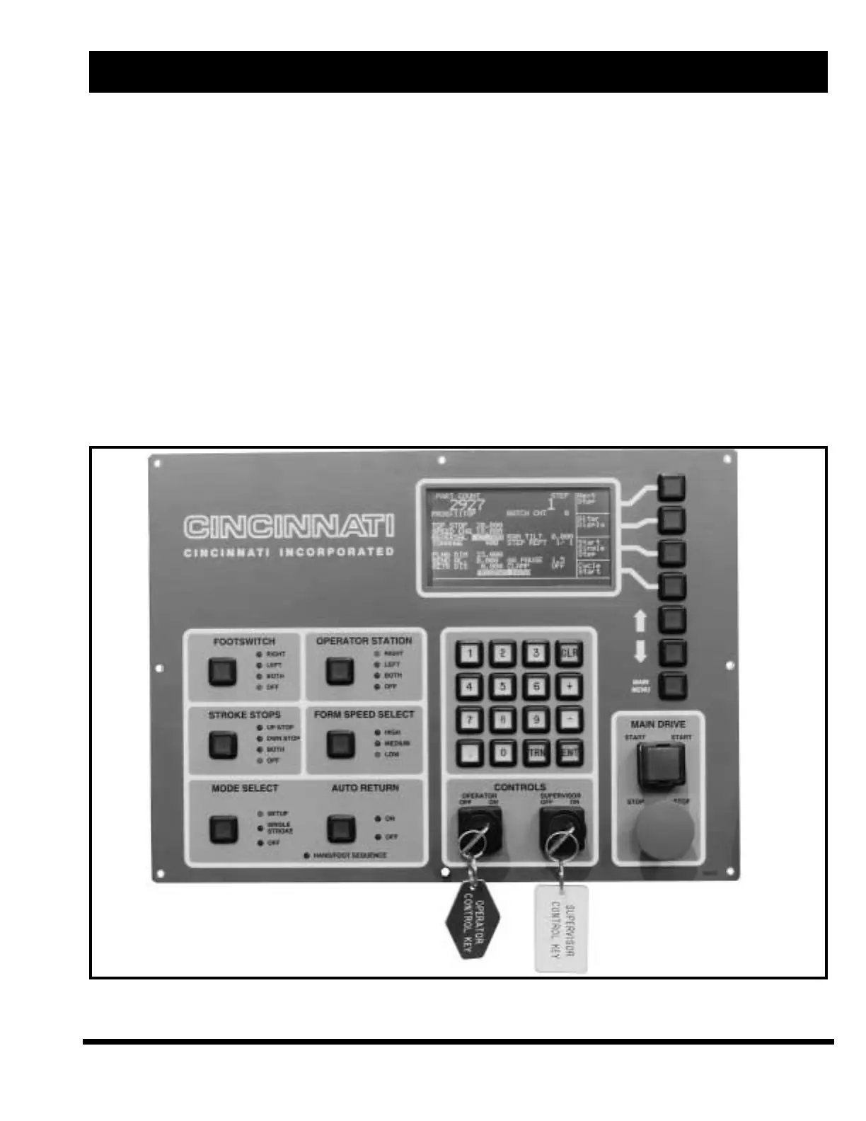
The Multi-Axis LCD Control Station (Figure 6-1)
controls the vertical motion of the ram and the
optional backgage.
CONTROLS
The Palmbutton Operator Station (Figure 6-2) is
located on the movable pedestal. The palmbutton
controls will actuate ram movement. The RAM UP
button will move the ram up on either the down or
up stroke. Lights are provided to indicate the direc-
tion of the next ram movement (except RAM UP
button).
A cable connected Footswitch Control (Figure 6-3)
is also provided to actuate ram movement. The
Footswitch Pushbutton Selector is located on the
FM Control Station.
The Electrical Enclosure Panel (Figure 6-4) con-
tains the machine disconnect switch and two indi-
cator lights – “Ground Connected” (push-to-test)
and “24 Volt Power Supply”.
EM-446 (N-08/99)
6-1
SECTION 6 MACHINE CONTROLS
FIGURE 6-1 – FM MULTI-AXIS LCD Control Station