The CNC Plate Gage is also furnished with a pair of
heavy duty gage blocks. They are non-adjustable
hardened steel assemblies, which are generally rec-
ommended for gaging large sheets or plates over
100 lbs. (45 kg).
The face of the gage fingers is the contact surface
and gaging surface for the workpiece when it is
pushed through the dies for gaging. The distance
from the face of the gage finger to the centerline of
the dies is the gage distance.
IMPORTANT: Do not gage from the front sur-
face of the aluminum gage bar due to wear
and possible damage of this surface.
It is generally recommended that two-point gaging
be used. This minimizes sheet edge camber effect
and allows greater flexibility in positioning gage
contact points. See Figure 5-9.
FIGURE 5-9 – Two-point gaging
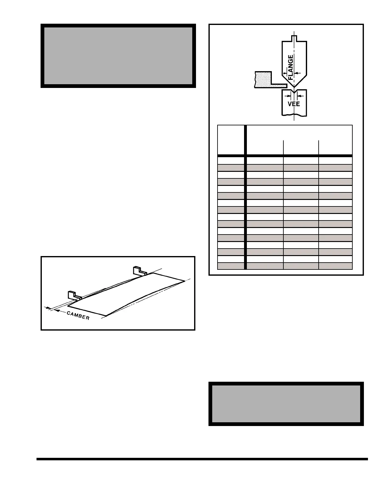
To select the gage finger for the forming job to be
run, refer to Figure 5-10. This chart provides the
minimum flange size it is possible to form with a
given size vee die.
FIGURE 5-10 – Minimum flange size
IMPORTANT: The selected gage surface should
be analyzed carefully to avoid interference
with the tooling and yet provide a large
enough target to ensure part contact.
ADJUST GAGE FINGER POSITION
Vertical position of the gage surfaces with man-
ual “R” are adjusted by turning the hand cranks
on each CNC Heavy Duty Backgage carriage
(Figure 5-11).
! ! ! DANGER ! ! !
! ! ! DANGER ! ! !
DO NOT REACH THROUGH DIE AREA TO
ADJUST “R”. GO TO REAR OF MACHINE TO
MAKE ADJUSTMENT.
! ! ! DANGER ! ! !
! ! ! DANGER ! ! !
DO NOT INSTALL OR REMOVE GAGE FINGER
OR GAGE ASSEMBLY BY REACHING THROUGH
DIE AREA. REMOVE GAGE ASSEMBLY FROM
GAGE BAR USING SPECIAL HAND TOOL FROM
FRONT OR GO TO REAR OF MACHINE TO MAN-
UALLY REMOVE GAGE ASSEMBLY.
5-5