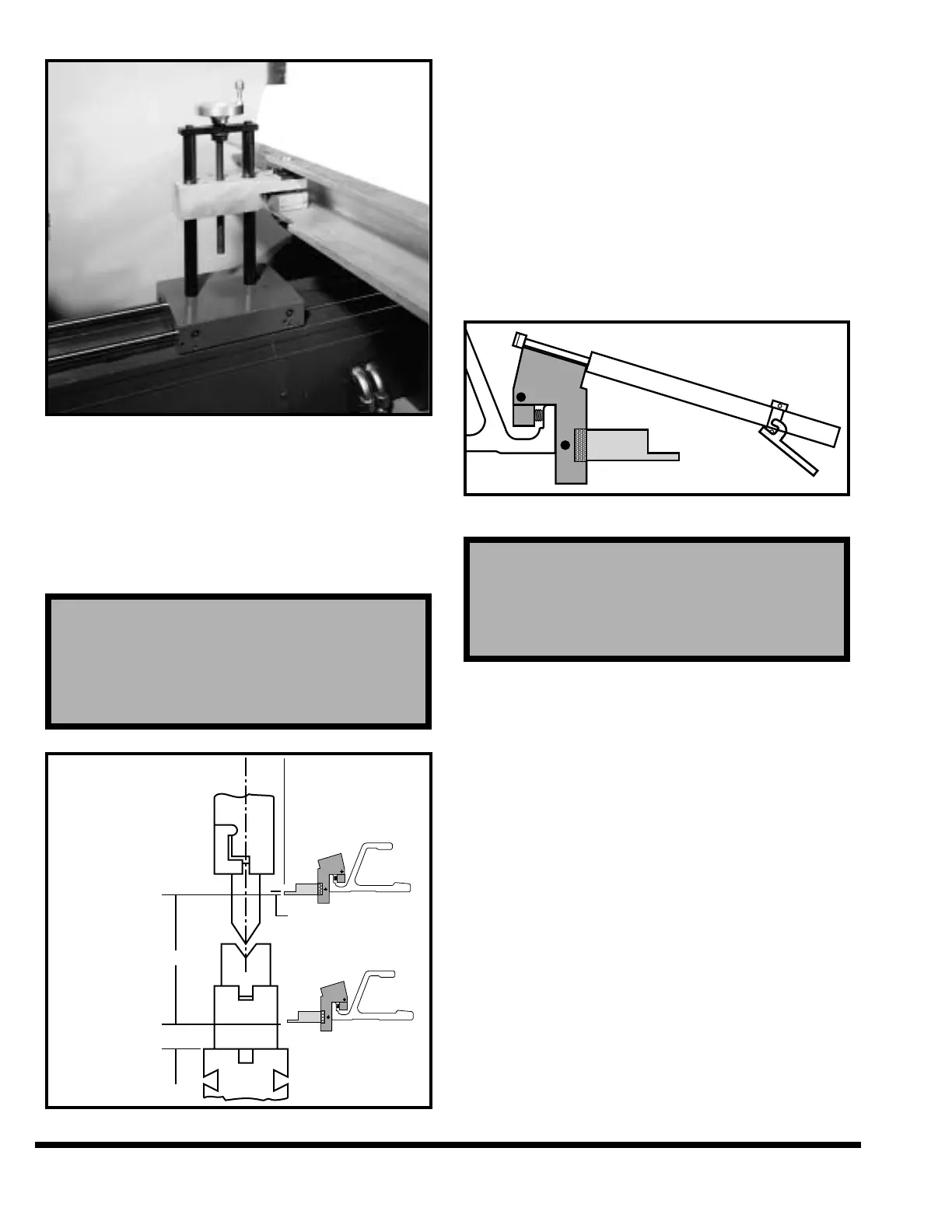
FIGURE 5-11 – Adjusting vertical gage position
Vertical position of the gage surfaces with power “R”
axis are adjusted with the program or they can be
adjusted with the gage jog softkeys. The best height
for the gages will depend upon the shape of the part
being formed. Standard adjustment limits are
shown in Figure 5-12.
FIGURE 5-12 – Adjusting gage surfaces
The gage finger assemblies should be positioned
left-to-right to contact the part being formed at the
desired gage points. Normally the two gage finger
assemblies should be spread as wide as possible to
provide the most accurate gaging. The gage finger
assemblies are moved along the gage bar by using
the gage positioning tool (Figure 5-13). This tool
releases the gage assembly clamp and holds the
assembly while it is being moved. The gage posi-
tioning tool is used to position the gage assemblies
from the front of the machine. The gage finger
assemblies are installed or remounted by using the
gage positioning tool.
FIGURE 5-13 – Gage positioning tool
Minor part flange differences (end-to-end) can be
corrected by adjusting the individual gage fingers
either forward (to shorten flange) or backward (to
lengthen flange). First remove the gage assembly
from the backgage bar. Loosen the finger by pulling
out the locking knob (Figure 5-7) and turning knob
counterclockwise. The adjusting collar has a total
range of .06” (1.5mm) adjustment.
Adjust the collar either forward or backward the
desired amount. Reseat finger shoulder tightly
against adjusting collar and tighten the locking
knob. All gages are shipped from the factory zeroed
from the centerline of the ram with the gage assem-
bly at .00” position.
Note: The locking pin spins freely unless it is pulled
out. This allows the knob to rest against the
backgage face, thus preventing the finger
from being unlocked while the assembly is in
position on the gage bar.
IMPORTANT: Do not use standard gage finger
assemblies when gaging plates or sheets
that weigh over 100 lbs. (45 kg) on the CNC
CAUTION
The following gage finger adjustments should
never be made while the gage assembly is in place
on the backgage. Always use the gage positioning
tool to remove the gage assembly.