Once the main parts have been moved to the area
where the press brake will be located, remove the
skids from the bed and ram. Leave any skids on the
housings.
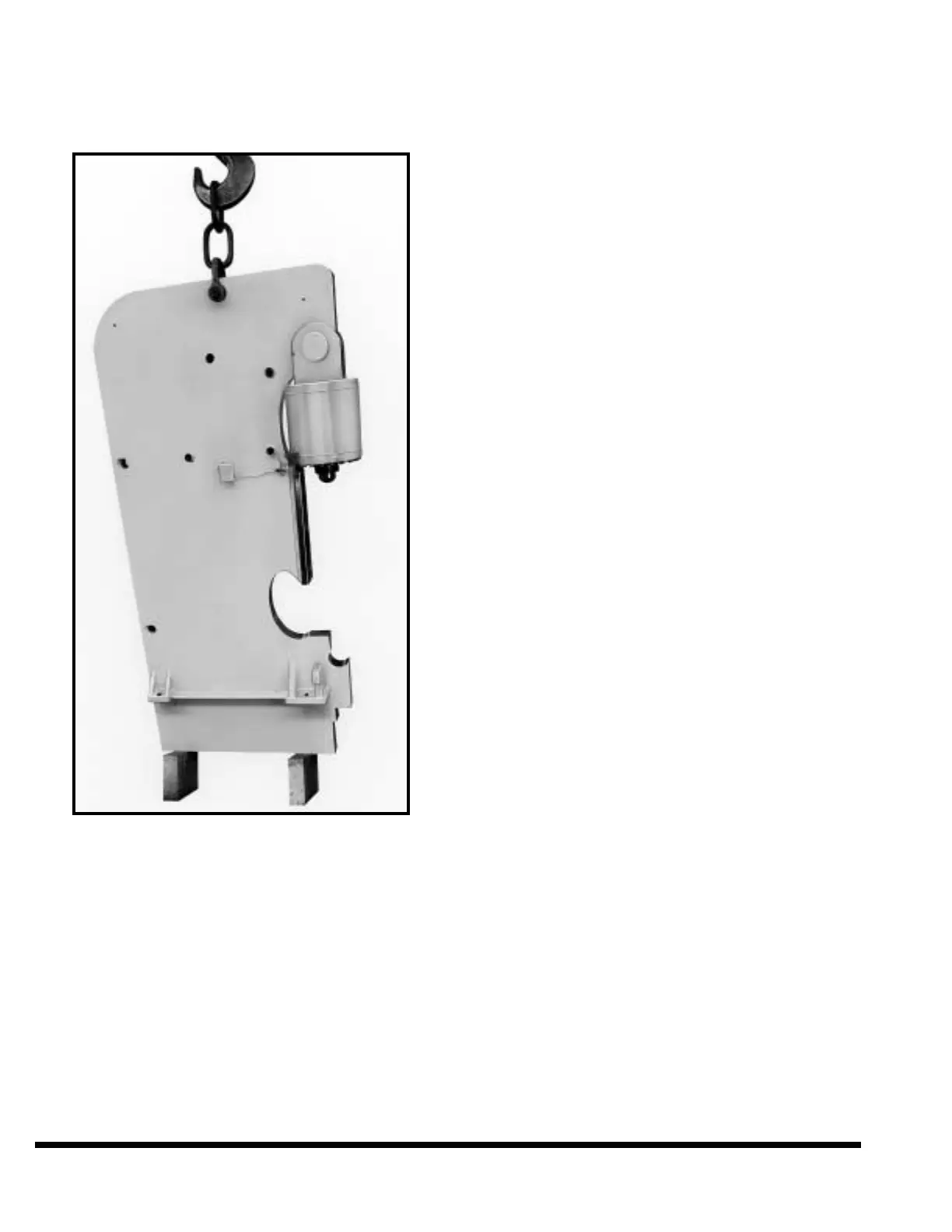
FIGURE 2-2 – Lifting the housings
FOUNDATION
A CINCINNATI FM Hydraulic Press Brake must be
provided with a rigid foundation to ensure that
alignment of the housings and cross framing mem-
bers is maintained. The foundation must support
the weight of the machine without cracking or set-
tling out-of-level.
For details of the foundation recommended for your
machine refer to the certified Foundation Plan
drawing. It is advisable, particularly in localities
where unusual soil conditions may exist, to have
your Foundation Plan approved by a local regis-
tered civil engineer.
As a final check before locating the FM Hydraulic
Press Brake on the foundation, see that the anchor
bolts in your foundation match the bolt hole spac-
ing in the housing feet. Check the width of the bed
pit and the distance from the centerline of the front
foundation bolts to the front edge of the bed pit.
They should agree with the dimensions shown on
the certified Foundation Plan drawing.
ERECTION - ASSEMBLED MACHINES
The 400FM through 14' (with standard housings)
Press Brakes are shipped with the bed bolted on
the rear of the machine.
Open the shim packages shipped with the machine
and remove the thickest shim from each package.
Place one shim at each foundation bolt location.
The top surfaces of the shims must be about level.
Thinner shims can be used to obtain this level con-
dition. Then place a 1/8” thick shim at the front
feet locations to deliberately make the front of
machine high. It is easier to raise the rear housing
feet to obtain final leveling when the FM Hydraulic
Press Brake is in position. As an option, it is rec-
ommended that a transit is used to establish that
all four pads are in the same plane.
Lift the machine with a crane to remove skids. If
no crane is available, secure against tipping as
soon as the skidded machine is placed on the
foundation and before skids are removed. To
secure against tipping use a block and tackle. Run
one from the housing lifting hole to the rear of the
machine and secure to a solid anchor in the build-
ing. Run another block and tackle from the other
housing lifting hole to the front and secure. To
remove skids, raise the machine in about 2” steps
with the aid of blocking and jacks of sufficient
capacity. On 400FM Press Brakes the jacks
should be placed under the front and rear of hous-
ings. Use leveling screws in housing feet for insert-
ing and removing jacks. On larger FM Press
Brakes the jacks should be placed under lifting
lugs on back of each housing and under the pro-
jection of rib welded to front housing feet and
housings. Block up housings, about 2" at a time,
until there is enough clearance to remove skids.
Lower machine by removing the blocking about 2"
at a time from alternate housings. Temporarily
bolt the machine in place on the foundation.
Remove the “X” type shipping braces bolted to front
of housings and thoroughly clean the protective
grease from front faces of the housings. Remove the
grease with a clean rag soaked in solvent, such as
mineral spirits, wipe with clean rags. A stiff brush
2-2