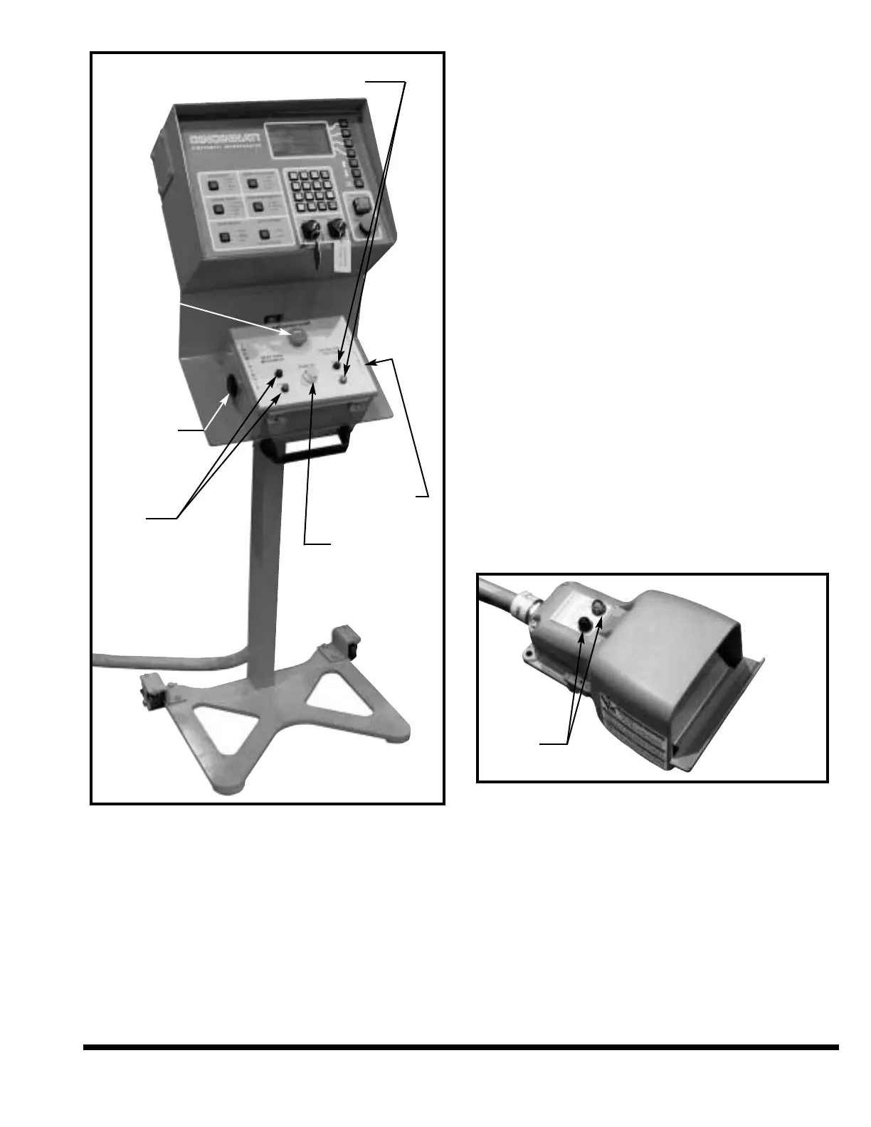
FIGURE 6-2 – Palmbutton Operator Station
EMERGENCY STOP Button: When this red
button is pressed, the ram, main drive motor
and gages will stop. The ram will stop on
either the DOWN or UP stroke.
NEXT RAM MOVEMENT Lights: These lights
indicate the direction of movement that the ram
is moving, or will move when an operator control
is depressed (except RAM UP button which over-
rides these lights). Red indicates down move-
ment and green indicates up movement. If no
light is illuminated and the machine is ON, a
light bulb is burned out. Advise Maintenance.
Do not operate the machine with non-func-
tional operation-related indicator lights.
FOOTSWITCH
This is a guarded operator control which controls
ram motion. It can be used in the SINGLE STROKE
mode of operation. The ram will move when the
footswitch is held depressed. It will continue to
move until it is released or the ram reaches top
stop position. If any of the STROKE STOPS are ON,
the ram will automatically stop at these positions.
To restart ram motion, the footswitch must be fully
released and depressed again.
The footswitch is made active by switching ON
the FOOTSWITCH selector on the FM Control
Station (Figure 6-1) to RIGHT, LEFT or BOTH.
With the selector in the “ON” position, the ram
can be cycled with the footswitch. In the “OFF”
position the ram cannot be cycled with the
footswitch. A red indicator light on the
footswitch indicates the footswitch is OFF and
an amber light indicates the footswitch is on. If
no light is illuminated and the machine is ON,
a light bulb is burned out. Advise Maintenance.
Do not operate the machine with non-func-
tional operation-related indicator lights.
FIGURE 6-3 – Footswitch (Handle removed for clarity)
ELECTRICAL ENCLOSURE
GROUND CONNECTED LIGHT: The low voltage
circuit is a grounded circuit. The illuminated
light indicates that the ground is connected (see
Figure 6-4). This is an internal chassis ground –
it does not indicate that the machine is ground-
ed to an adequate earth-ground. If no light is
illuminated and the machine is ON, a light
bulb is burned out. Advise Maintenance. Do
not operate the machine with non-function-
al operation-related indicator lights.
6-5
OPERATOR STATION ON / OFF
STATUS INDICATOR LIGHTS
LEFT
PALMBUTTON
RAM
MOVEMENT
INDICATOR
LIGHTS
EMERGENCY
STOP BUTTON
RIGHT
PALMBUTTON
RAM UP BUTTON
ON / OFF
INDICATOR
LIGHTS