Note: Short, lightweight dies may be installed
as a set and slid into position.
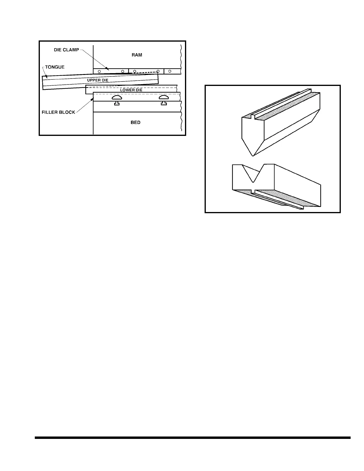
FIGURE 5-5 – Die positioning
✦ Moderately tighten the ram die clamp nuts to
prevent the upper die from falling when the
ram is raised. Also tighten the appropriate
filler block set screws to secure lower die to the
filler block. Turn the OPERATOR CONTROLS
selector to “ON”.
✦ Use the RAM UP button to raise the ram .125”
to .25” (3.2 to 6.4mm). Turn the OPERATOR
CONTROLS selector to “OFF” and remove key.
✦ Visually align the upper and lower dies. Shift
the filler block front-to-back to obtain rough die
alignment.
✦ Turn OPERATOR CONTROLS selector to “ON”.
✦ Inch the ram down using palmbuttons until the
upper die is seated. In SET-UP MODE, the
machine’s hydraulic pressure is limited to 10%
of the machine’s capacity. For example, for a
centered die set on a 400 ton FM, the tonnage
is thus limited to 40 tons (355.8kN); however, if
centered under one housing, the tonnage is
thus limited to 20 tons (177.9kN).
IMPORTANT: When seating dies it may be
advisable to place wood blocks or soft
metal between the dies to prevent damage
to the dies. Short dies must have sufficient
shoulder area to prevent sinking into the
ram, bed or filler block.
The hydraulic components and machine
frame members are safeguarded against
overload by a relief valve in the hydraulic
circuit. However, care must be taken to pro-
vide enough area under upper and lower
dies to prevent them from sinking into the
ram nose or bed top due to highly concen-
trated loads. This is the shaded area
shown in Figure 5-6. The minimum area
(sq. in.) for each die to prevent sinking may
be calculated by this formula:
Die Area = MAXIMUM TONNAGE / 15
An example for a 400 ton machine, the
minimum die area for a capacity load is
400 divided by 15, or 26.7 square inches.
FIGURE 5-6 – Seating dies
✦ Fully tighten the die clamp nuts after seating
the upper die. Check the shoulders of the dies
with a .002” (.05mm) feeler gage to make sure
they are seated tightly, both front and back.
✦
Run the ram upwards to provide clearance
between dies to remove wood blocks or metal
strips if used. Then move ram down to establish
clearance equal to at least the metal thickness.
Check the front-to-back die alignment over the
full length of the dies. Realign if necessary. Feel-
er gages should be used to measure front-to-
back die clearances between the upper and lower
dies at both ends and at the center of the dies.
✦ Tighten the filler block to the bed.
✦ Tighten the lower die to the filler block.
GAGING - OPTIONAL BACKGAGES
There are two types of optional backgages available
on the FM, the CNC Plate Gage and the CNC Heavy
Duty Backgage. The X-axis (front-to-back) position-
ing is programmable through the FM’s Multi-Axis
Control. The R-axis (vertical) is also programmable
on the CNC Plate Gage and the CNC Heavy Duty
Backgage when ordered with the optional Program-
mable R-axis feature.
5-3