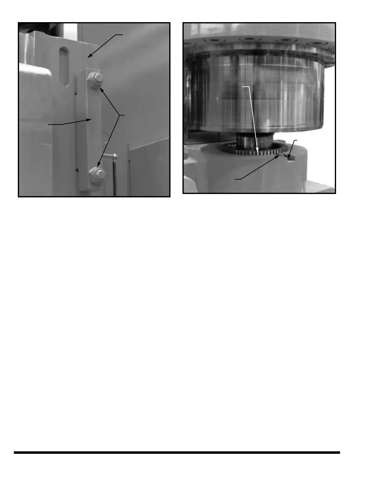
FIGURE 9-10 – Swivel end-guide bearing
1. Adjust swivel end-guide clamp by tightening
the two hex nuts evenly until they are snug,
monthly.
2. Backoff both nuts one-quarter turn. This will
allow about .002” to .003” (.051mm to
.076mm) running clearance.
BALL SEAT ADJUSTMENT
To adjust for wear in the piston ball seat:
1. Turn the main drive motor and disconnect
switch on main electrical enclosure OFF. Lock-
out the main disconnect.
2. Select jacks of sufficient capacity to lift the
weight of the ram and ram slides. Place the
jacks at each housing. Protect the finished sur-
faces of bed and ram with wood or soft metal.
3. Raise the jacks until piston ball ends are tight
in the ball sockets.
4. Loosen the lock screw and pry lock plate away
from adjusting nut.
5. Turn adjusting nut clockwise by tapping with a
brass rod until it is tight. Then backoff one
notch. Tap lock plate into the notch and tight-
en lock screw.
6. Repeat Steps 4 and 5 for the other ball seat.
7. Remove jacks.
FIGURE 9-11 – Ball seat adjustment
RAM LINEAR TRANSDUCER
(POTENTIOMETER) ADJUSTMENT
IMPORTANT: This procedure must be done when-
ever the ram clamp bolts are loosened.
1. Set the machine controls:
OPERATOR STATION RIGHT ON
FOOTSWITCH OFF
MODE SELECT SETUP
OPERATOR CONTROLS Selector ON
SUPERVISOR Selector ON
2. Start machine by turning main disconnect ON
and pressing MAIN DRIVE “START” button.
3. Clean the bed top and place a 8.000” - 14.000”
(203.2mm - 355.6mm) steel spacer (or any two
identical length spacers longer than the mini-
mum closed height of the machine) between the
bed and ram at each end, in line with the trans-
ducer rods, and centered under the ram nose.
Check that the ram nose, and not (just) the ram
die clamps, are resting tightly on the spacer(s).
Check with a .001” (.025mm) to .002” (.05mm)
feeler gage. Both ends must be checked. See
Figure 9-12.
4. Use the Palmbutton Operator Station to cycle
the ram down and the “RAM UP” button to
cycle the ram upwards.
5. Jog the ram down until it is about .50” away
from the spacers.
9-8
RIGHT SLIDE
ADJUSTING
NUTS
END-GUIDE
BEARING
CLAMP
ADJUSTING NUT
LOCK PLATE
LOCK SCREW