Plate Backgage. Damage to adjustable fin-
ger holder could result. Use Plate Gage
Blocks for these applications. Never allow
workpiece to contact aluminum gage bar.
Bar damage could result.
PROGRAM GAGE POSITION(S)
Now that the gage assemblies and the gage fingers
have been positioned left-to-right and vertically, the
backgage can be programmed for its front-to-back
position(s).
The actual position of the gage in relation to the
tooling is selected when entering a program into the
Control. This procedure is described under MULTI-
AXIS CONTROL PROGRAMMING, “FLANGE
DIMENSION” and “BEND ALLOWANCE” in SEC-
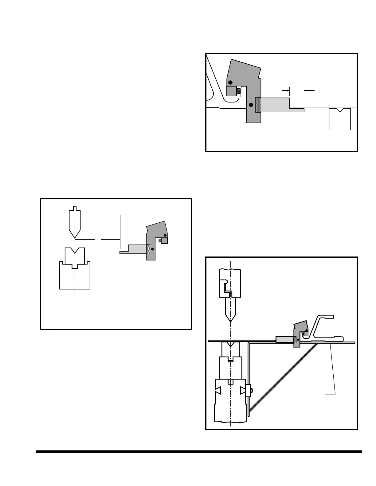
TION 7. Actual gage dimension from the centerline
of the tooling to the gage surface is determined by
two program inputs, flange dimension and bend
allowance. Bend allowance input is the sum of bend
allowance and finger offset. See Figure 5-14.
FIGURE 5-14 – Figuring actual gage dimension
Normally the control will position the gage bar rel-
ative to the ram centerline for a gage surface that is
4.000” (102mm) in front of the face of the gage bar.
This is correct when using standard gage finger
assemblies with 3.000” (76mm) long fingers, along
with tooling that is centered on ram centerline.
Shorter gage assemblies require negative offset and
longer assemblies require positive offset values.
Plate Gage Blocks require a -3.000” (-76mm) offset
since their gage surface is 1.000” (25.4mm) in front
of the gage bar. (Note: Put this offset in the Bend
Allowance value.)
The 1/4” (6.4mm) gage finger can also be used as a
sheet support as shown in Figure 5-15, for light-
weight sheets.
FIGURE 5-15 – Gage finger used as sheet support
WORK SUPPORTS
Two work supports for light gauge material are fur-
nished with the optional backgages. They are
intended to be used in the rear of the bed when long
backpieces (which droop away from the gage sur-
face) are formed. These supports attach to rear
dovetail slots in the bed and should be positioned
at same height as the top of lower die. Figure 5-16
shows a typical work support set-up. Make sure
backgage bar clears the work support.
FIGURE 5-16 – Typical work support setup
dimension must be offset in the program.