will get into the corners. Do not use an air hose
because the pressure could drive grit and dirt into
the bearing surfaces.
The front vertical bed mounting faces of the hous-
ings must be plumb. This can be checked with the
level in squaring head of an ordinary machinist’s
square or with any level that can be used on a ver-
tical surface. If the housings are not plumb, loosen
the nuts on foundation bolts. Use leveling screws in
housing feet to raise or lower machine. Do not allow
machine to permanently rest on these screws. On
larger machines place a jack under lifting lug to
raise housing. Insert flat steel shims under the
housing feet as required. Lower housings and
retighten foundation bolt nuts. Recheck the plumb
on housing faces and repeat above procedure if
necessary until the housings are plumb.
Remove the bed from rear of housings using a
chain or cable of adequate capacity. DO NOT USE
HOUSING SLOT IN THE BED TO LIFT THE BED.
Remove the bed shoes and bed bolts from shipping
box. Clean the bearing surfaces of the housings
and the matching bed surfaces, and the bed shoes
and bolts. Carefully lubricate all finished surfaces
of the housings where the bed fits. Also lubricate
top and bottom surfaces of bed shoes. Use EP #2
Lithium grease (C.I. grease H-2EP). Place bed shoes
into position on the housings. Match the markings
on housings and bed shoes. Place the bed into posi-
tion on housings and insert bed bolts into bed.
Loosen all foundation bolt nuts and tighten bed
bolts securely. Retighten the foundation bolt nuts
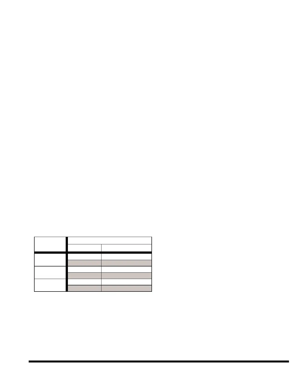
securely. See Figure 2-3 below for bed bolt and
foundation nut seating torques.
FIGURE 2-3 – Seating torques
Check your work with feeler gages. There should be
no clearance between the bearing surfaces of the
housings and bed. If there is clearance, either the
bed bolts are not tight or there is grit between the
bearing surfaces. There should also be no clear-
ance between the bed shoes and the bed.
Place a jack between bed top and the bottom of
both ram slides. Protect the finished surfaces with
wood or soft metal. Loosen, do not remove, the
screws holding four ram slide clamps to ram slides.
Remove plastic laminate shipping strips from under
ram slide clamps. Pry ram slides out enough to
remove the plastic laminate from between the ram
slides and guides.
IMPORTANT: These plastic laminate shipping
strips must be removed before running the
machine.
Use the recommended cleaning solvent to flush
protective grease from between slides and guides.
Allow surfaces to dry and lubricate with oil. Push
ram slides back against guides. Securely tighten
the ram slide clamp bolts. Lower both jacks equal-
ly. If ram follows the jacks down, do not allow one
end to get out-of-level more than one inch. Remove
the jacks.
Tighten the lock-down screws between the housings
and bed. They are located at the bottom of each
housing where the housing fits through the bed.
The encoder lower mounting brackets were removed
for shipment. A CINCINNATI INCORPORATED Ser-
vice Representative will install and adjust the
encoders at start-up.
Erection of assembled machines is completed. Pro-
ceed to the information on CLEANING.
ERECTION - DISASSEMBLED
MACHINES
The 400FM x 16' and larger press brakes are
usually shipped disassembled. CINCINNATI
INCORPORATED Service Representative should
be scheduled to assist with installation of
machine. Before setting-up the housings, open
the shim packages. Remove the thickest shim
from each package. Place one shim at each foun-
dation bolt location. The top surfaces of the
shims should be about level. Thinner shims can
be used to obtain this level condition. Then
place a 1/8" thick shim at the four front feet
locations to deliberately make the front of
machine high. It is then much easier to raise the
rear housing feet to obtain final leveling when
the press brake is in position. As an option we
recommend using a transit to establish that all
four front and rear pads are in the same plane.
The cylinders and slides should be assembled to
each housing. Most machines are shipped in this
manner. Either housing may be set up first. To lift
housing, use a clevis as shown in Figure 2-2. If the
clevis is not available, an adequate strength cable
should be used in the same housing hole. Be sure