to protect finished surfaces from damage. Raise the
housing and rest it on two blocks as shown in Fig-
ure 2-2. Once the housing is vertical, remove nuts
holding the long vertical skids. Pull the skids from
the bolts, then take off the two cross timbers. Place
housing over the foundation bolts on top of shims.
Place flat washers on each foundation bolt and
start nut on bolts. To ease later assembly of bed,
plumb housing front and side. This can be checked
with the level in squaring head of an ordinary
machinists' square or with any square that can be
used on a vertical surface. Use flat steel shims
under the housing feet as required to plumb both
surfaces. Tighten the foundation bolt nuts with
wrench. Remove lifting device.
Erect the other housing using the same procedure
as for the first housing. Place a flat washer on each
foundation bolt and start nut on bolts. Do not tight-
en nuts. Shim housing to obtain plumb in relation
to first housing and distance between housings.
Carefully check distance between housings. This is
measured from inside finished surface where bed is
attached.
Example: For a 600FM x 12'. This measurement is
12'-6". The measurement can be taken
from the machined slots in rear of bed.
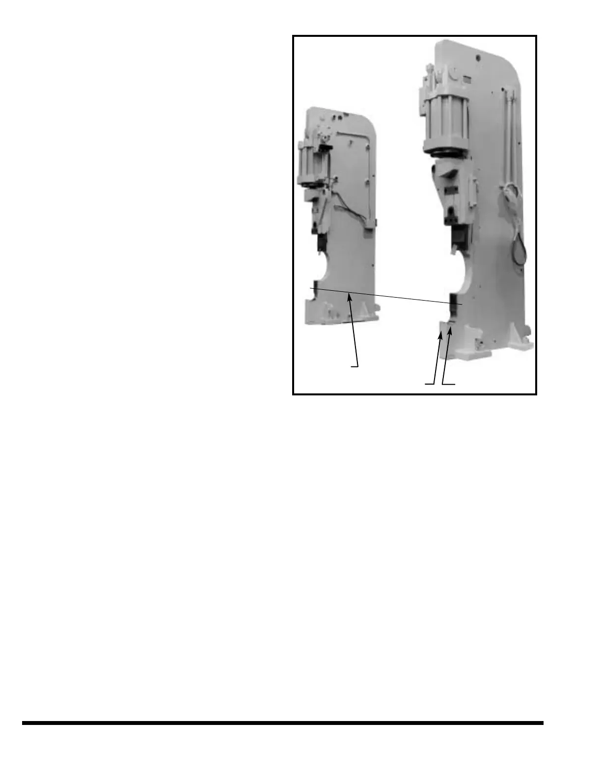
Tighten foundation bolt nuts with wrench. Align
both housings as shown in Figure 2-4 by shifting
housings as required.
Machines with Auto Crown: The rear deflection
plate should be placed in the foundation pit at its
approximate location before the bed is installed.
Remove bed shoes and bed bolts from shipping box.
Clean bearing surfaces of housings and matching
bed slot surfaces, and the bed shoes and bolts.
Carefully lubricate all finished surfaces of housings
where the bed fits. Also lubricate top and bottom
surfaces of bed shoes. Use EP #2 lithium grease (C.
I. grease H-2EP). Place bed shoes into position on
the housings. Match the markings on housings and
bed shoes. Place bed into position on the housings.
Insert bed bolts into bed. Loosen all foundation bolt
nuts and tighten bed bolts securely. Retighten
foundation bolt nuts securely. See chart (Figure 2-
3) for bed bolt and foundation nut seating torques.
Check your work with feeler gages. There should be
no clearance between vertical bearing surfaces of
the housings and bed. If there is clearance, either
the bed bolts are not tight or there is grit between
bearing surfaces. There should be no clearance
between bed shoes and the bed. If there is clear-
ance, remove the bed.
FIGURE 2-4 – Aligning housings
Determine and correct the cause of clearance.
Replace the bed as previously described. Recheck
clearance.
Tighten the lock-down screws between the hous-
ings and bed. They are located at the bottom of
each housing where housing fits bed.
CINCINNATI Hydraulic Press Brakes are leveled by
placing flat steel shims of proper thickness under
the housing feet as required. Use a precision level
graduated in .0005" per foot – not a carpenter's or
machinist's level. Always wipe level and bed surface
clean before placing the level.
The 400FM machines can be raised or lowered by
using leveling screws in the housing feet. Use at
least a two foot length of pipe on the wrench. On
larger machines jack lugs on sides and back of the
housings are used for this purpose. The foundation
bolt nuts must be loosened, not removed, before
jacking the press brake. Before checking the level of
the machine the foundation bolt nuts must be
securely tightened.
2-4
ALIGN
THESE
SURFACES
MARKING HOUSING SEAT