CINCINNATI INCORPORATED Service Department.)
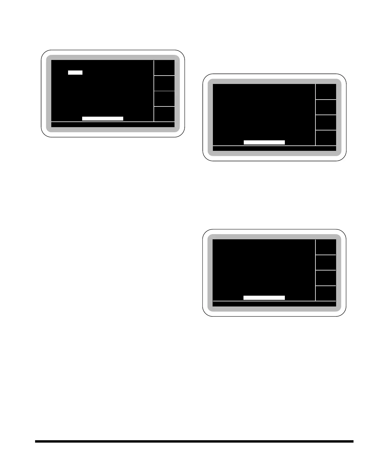
The user page of the multi-axis CONFIGURATION
screen is shown:
Units: A “Change Units” softkey is displayed
that toggles the measurement system to be used
in programming the control. When INCH is dis-
played, all linear measurements are in inches
and the tonnage values are in Tons (short).
When METRIC is displayed, all measurements
are in millimeters and tonnage values are in
Metric tons.
The control will store all values in English units.
Some error may be expected in the least signifi-
cant digit when metric values are displayed. This
may be noticeable when attempting to enter a
value close to the minimum or maximum when
in metric mode. The control will power-up set for
the last units selected.
Language: A “Change Language” softkey is dis-
played that toggles the language used for all
messages between ENGLISH, SPANISH and any
other languages added. The control will power-
up set for the last language selected.
Backgage: A “Toggle Gage” softkey is displayed to
select OFF or ON. OFF will disable all backgage
movement from program control. It still allows
the backgage dimensions to be entered. ON
allows gage movement under program control.
Special Auto Return: The Special Auto Return
mode (see SECTION 6 for details) can be enabled
or disabled. To prevent this mode from being
selectable, choose “DISABLED”.
Serv Access Code: This softkey allows entry of
the service access code to access machine para-
meters. This has to be performed by a Service
Representative of CINCINNATI INCORPORATED.
Diagnostics: Pressing this softkey’s button
takes you directly to the DIAGNOSTICS MENU
display.
DIAGNOSTICS
Additional softkeys are provided for accessing a
DIAGNOSTICS screen. The DIAGNOSTIC screen
contains functions for verifying correct operation of
the control.
SYSTEM ERROR
This screen can be used to diagnose a control fault.
When a fault occurs, information may be recorded
here. On power-up after a fault, this screen will be
displayed. The information on this screen should
be recorded and then cleared.
AXIS/ VALVE POSITIONS
This screen shows the current state of the ram and
gage axis as well as the status of the solenoid
valves. It is possible to run the machine while dis-
playing this screen to view sequencing of the valves
and axis. Some values, such as the linear trans-
ducers (POT) positions, may not update fast enough
to show the current position. These values may
reflect the true position only when the ram has
reached a programmed position. This screen shows
the lowest reversal position for the last ram stroke
as well as current tonnage and peak tonnage for the
last stroke.