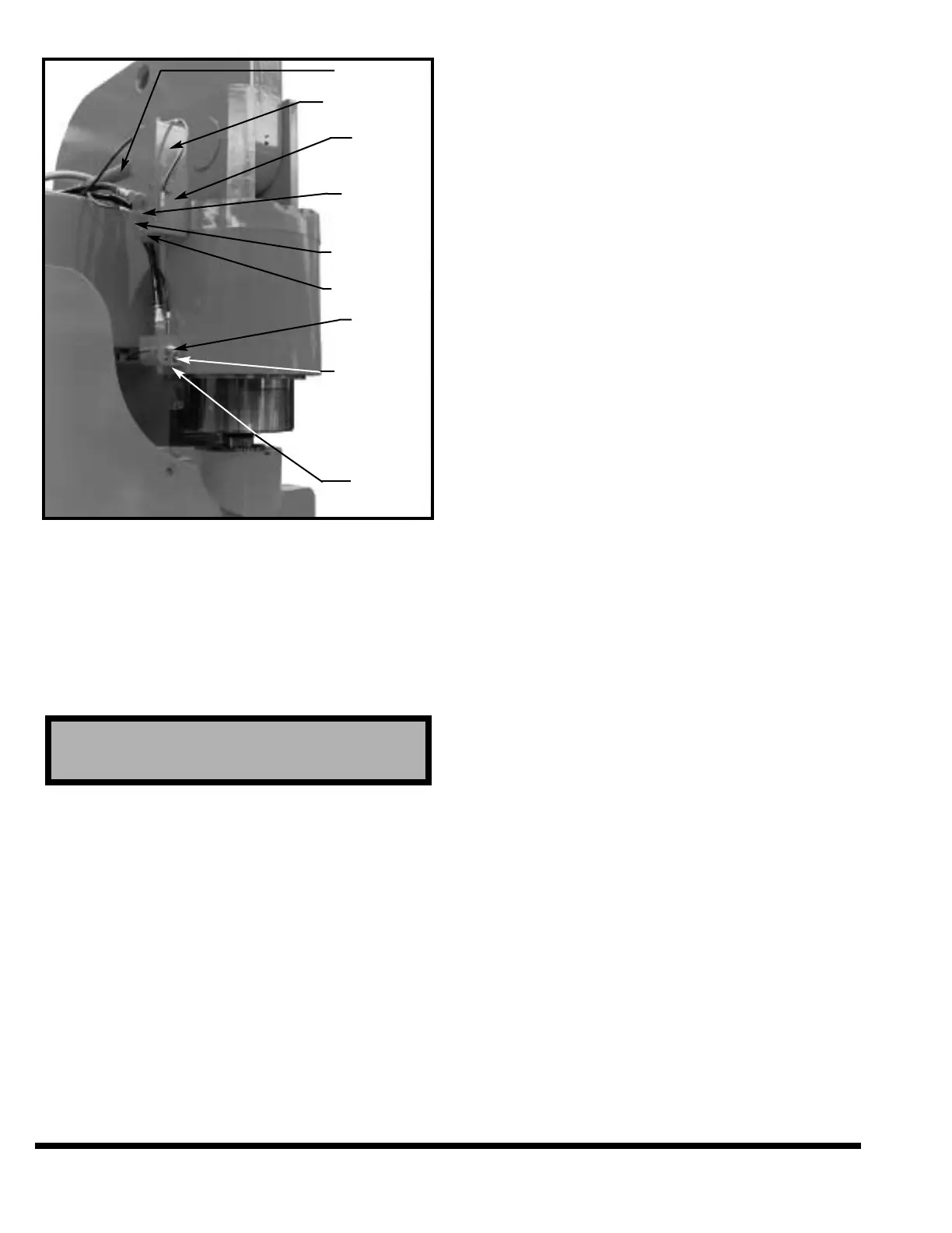
FIGURE 9-7 – Counterbalance pressure check
9. After setting the pressure, cycle the ram a
number of strokes and recheck both counter-
balance pressures. Remove gage before cycling
ram to up position.
10. Turn OFF motor/pump and remove pressure
gage.
MAIN RELIEF PRESSURE
This pressure is controlled by a preset valve and
cannot be adjusted. Contact a CINCINNATI
INCORPORATED Service Representative if this
pressure must be checked.
AIR FILTER / BREATHER
The air filter/breather is located on the auxiliary
cover plate. (See Figure 9-6A and 9-6B.) The dis-
posable, canister-type breather/filter should be
replaced about every 2000 hours of machine
operation.
OIL LEVEL / TEMPERATURE
SWITCH
If the oil drops to the minimum allowable level,
an error message will appear on the display and
will cause the main drive to shut down. The
cause for the low oil level should be found and
corrected. Fill reservoir to the proper level.
If the operating temperature reaches the maxi-
mum level, an error message will appear on the
display. Stop machine operation as soon as pos-
sible and locate the cause of the excessive heat. If
the oil temperature continues to climb and reach-
es 150° (66°C), the main drive will shut down.
OIL COOLER
The oil cooler is an air-type heat exchanger.
Depending on the tonnage and machine configura-
tion, there may be two (2) heat exchangers. The
heat exchanger is equipped with a thermostatically
controlled electric fan which is operable only when
the motor/pump is running. The thermostat is set
to start the heat exchanger motor at approximately
135°F (57°C) oil temperature. A furnace type air fil-
ter is installed between the fan and the core of the
exchanger. The filter should be changed as
required. See Figure 9-6A and 9-6B.
HYDRAULIC UNIT OPTIONS
OIL HEATERS (Optional)
Oil heaters are recommended for cold start-ups and
cold running conditions (see temperature chart in
“HYDRAULIC OIL” section). It is an immersion-type,
thermostatically controlled, and is used indepen-
dently of the motor drive. Depending on the
machine length and/or options, there may be two
(2) heaters.
CYLINDERS
Cylinders on the CINCINNATI FM Press Brake are
shown in Figure 9-8. The inner piston is attached
to the fixed upper cylinder head and does not move.
The outer piston is attached to the ram, moving in
the cylinder and in relation to the inner piston. For
information to replace piston rod seals, contact
CINCINNATI INCORPORATED Service Department.
CAUTION
Do not leave gage permanently attached to test port.
9-6
PREFILL PIPE
PREFILL VALVE
RIGHT
CYLINDER
MANIFOLD
PILOT
SWITCHING
VALVE
TEST PORT #2
TEST PORT #1
COUNTER-
BALANCE
VALVE
COUNTER-
BALANCE
MANIFOLD
BLEED VALVE
TEST PORT #3
(BEHIND
COUNTER-
BALANCE
MANIFOLD