3. Recheck that all dies are removed.
4. Use the Palmbutton Operator Station to cycle
the ram down and the “RAM UP” button to
cycle the ram upwards.
5. Move ram up using RAM UP button to top stop.
6. Install 0-1000 PSI range pressure gage with a
female quick-disconnect into either test port
#3. Both must be checked.
7. The counterbalance pressure is checked while
running the ram down in SET-UP. The proper
pressure can be determined by adding 100 PSI
to the pressure required to hold the ram up
while the motor/pump is turned off. If very
heavy upper dies are to be used in the machine,
consult CINCINNATI INCORPORATED for infor-
mation to set the counterbalance pressure.
8. To adjust the pressure, loosen the locknut and
turn adjustment screw on counterbalance
valve. Turn adjusting screw clockwise to
increase and counterclockwise to decrease
pressure. Tighten the locknut.
CAUTION
Do not run ram up with gage attached.
9-5
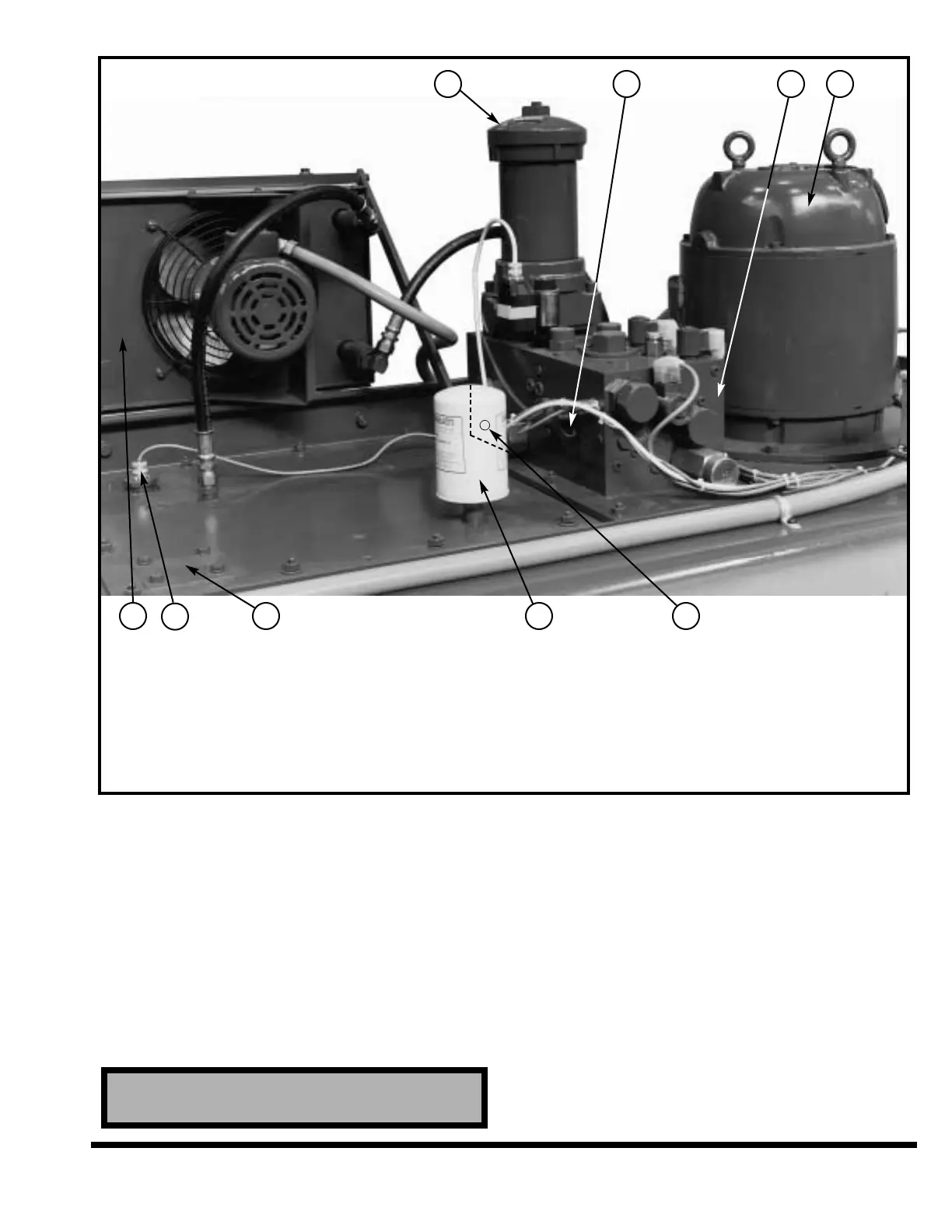
1. HIGH PRESSURE FILTER
2. TEST PORT #5
3. MAIN MANIFOLD
#1 SOLENOID - DOWN VALVE
#2 SOLENOID - UP VALVE
#5 SOLENOID - PILOT VALVE
#6 SOLENOID - SAFETY DUMP VALVE
VALVISTOR - SPEED & LEVEL CONTROL VALVE
#9 SOLENOID - DECOMPRESSION VALVE
PRESSURE TRANSDUCER
3. MAIN MANIFOLD (Continued)
MAIN RELIEF VALVE
MANUAL MANIFOLD BLEED VALVE
4. MOTOR / PUMP
5. TEST PORT #4 (Behind Air Breather / Filter)
6. AIR BREATHER / FILTER
7. LOCATION FOR OPTIONAL OIL HEATER
8. OIL LEVEL / TEMPERATURE SWITCH
9. AIR-COOLED HEAT EXCHANGER
FIGURE 9-6B – Hydraulic reservoir components (For Hydraulic Speed Package & 1000 - 2000 FM)
1 2 3 4
9
8
7 6 5