3. For more information on “KERMIT”, see: “KER-
MIT - A FILE TRANSFER PROTOCOL” by Frank
Da Cruz, Digital Press - Order #EY-6705E-DP,
ISBN #0-932376-88-6.
4. Order KERMIT software from KERMIT Distribu-
tion, Columbia University Center for Computing
Activities, 612 West 115
th
Street, New York, NY
10025. MS DOS version of KERMIT can be
downloaded at no charge from Columbia Uni-
versity’s website: www.columbia.edu/kermit/.
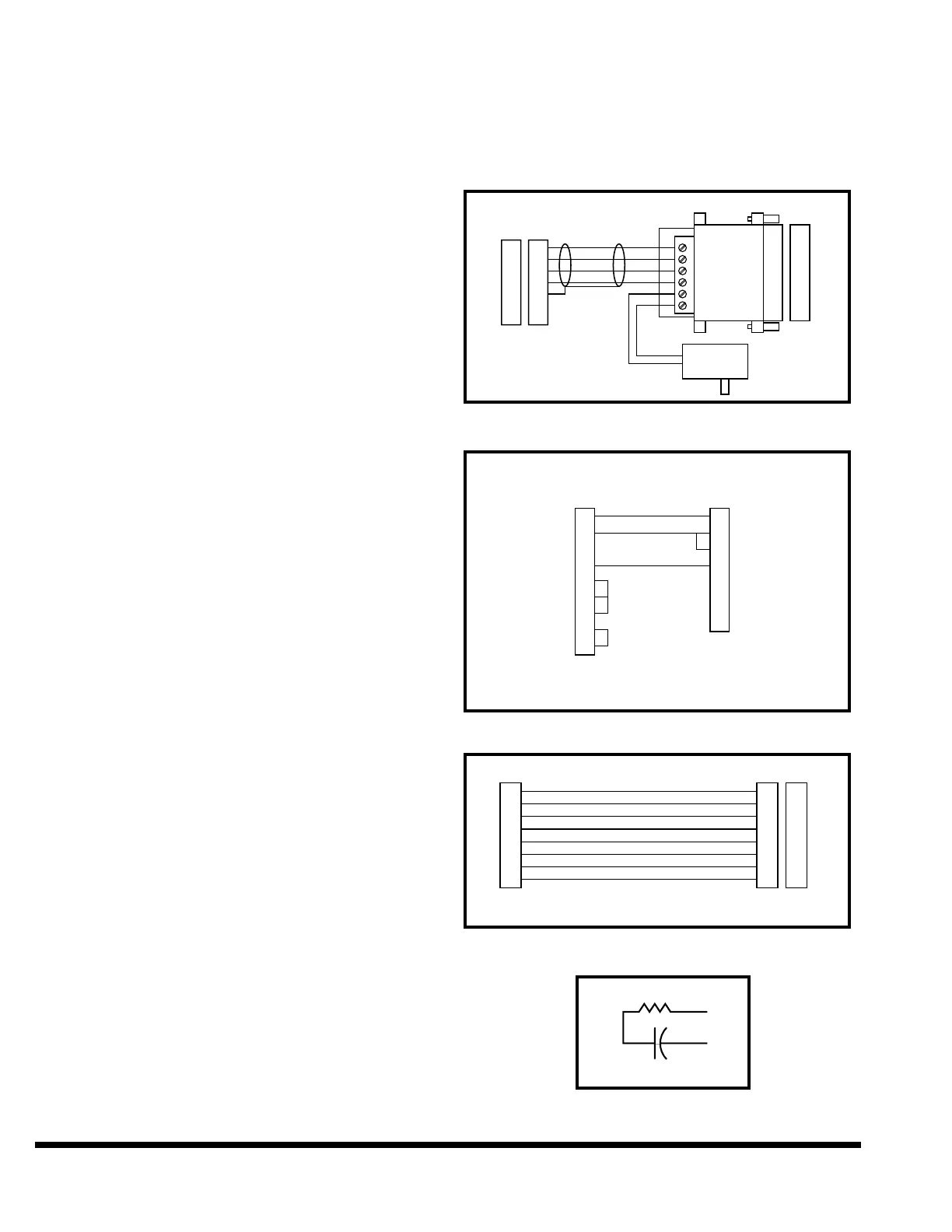
CABLE ASSEMBLY
The recommended cable configuration is shown in
Figure 9-14. It consists of a female 9-pin "D" type
connector, wired to an optically isolated RS-
232/RS-422 converter which can be used with
most 25-pin IBM PC and compatible serial port
connectors. TDA and TDB are sometimes referred
to as TD- and TD+ and RDA and RDB are referred
to as RD- and RD+. Belden 9502 (or equivalent) two
pair cable should be used for runs up to 1000 feet.
For runs longer than 1000 feet, Belden 8102 low
capacitance cable should be used. The adapter
cable shown in Figure 9-16 can be used to connect
the 25-pin RS-232/RS-422 converter to a 9-pin AT
style serial port connector.
The RS-422 differential signal is preferable over
RS-232 because RS-422 can be used with much
longer cables and at a higher baud rate than RS-
232. The optical isolation provided by the con-
verter eliminates ground difference problems
which can occur when connecting electronic
equipment together that are plugged into differ-
ent AC power distribution networks.
On very long cable runs, line termination is
sometimes necessary. Figure 9-17 shows the rec-
ommended dynamic termination network which
should be connected only at the receiving end of
the cable between RDA and RDB. Static termina-
tion devices, consisting of a resistor without the
capacitor, are not recommended because of the
excessive power required.
The RS-232/RS-422 Converter (Model 422NOICR),
12V Power Supply (Model 422PS2), and the PC-AT
to DB-25 Adapter Cable (Model 232 CAMS) can be
ordered from:
B & B Electronics Manufacturing Co.
4000 Baker Road
P.O. Box 1040
Ottawa, IL 61350
Tel.: (815) 434-0846
Fax: (815) 434-7094
For short cable runs the RS-422 signal can be
converted to RS-232 by connecting RDB to SG
and using only the TDA and RDA signals as
shown in Figure 9-15. A two pair cable should
still be run in case a problem would occur which
required converting to RS-422.
FIGURE 9-14 – Recommended Configuration
FIGURE 9-15 – Optional Configuration
FIGURE 9-16 – Adapter Cable
FIGURE 9-17 – Termination Network