Start leveling by checking the setting of the
machine lengthwise. Place level in the center of bed
parallel to edges of bed. Level the machine length-
wise by placing the required metal shim under the
low housing feet, both front and back. Let the press
brake down and recheck level. Repeat until
machine is level lengthwise.
Level the press brake front-to-back with level cross-
wise on bed as shown in Figure 2-5. Check first
with level at right end of machine and then at left
end. Add or remove shims under the front or back
housing feet as required. Level readings on both
ends of bed must be alike within .001". Recheck
lengthwise level and repeat above procedure until
machine is level in all directions.
FIGURE 2-5 – Leveling front-to-back
If this machine is equipped with Auto Crown
(optional), the two deflection plates and cylinder(s)
must be installed at this time. Install the deflection
plate pins in the bed bores with the edge of the pins
protruding from the rear of the bed far enough to
hold the spacer rings. Grease fittings must face
toward rear of machine if pins are below floor. Align
the rear deflection plate so the pins can be pushed
into the matching deflection plate bores. Next,
install the front spacer rings and front deflection
plate onto the deflection pins. Bolt the front and
rear cap plates onto the pins and deflection plates.
Install the Auto Crown cylinder(s) and bolt in place
to the mounting brackets.
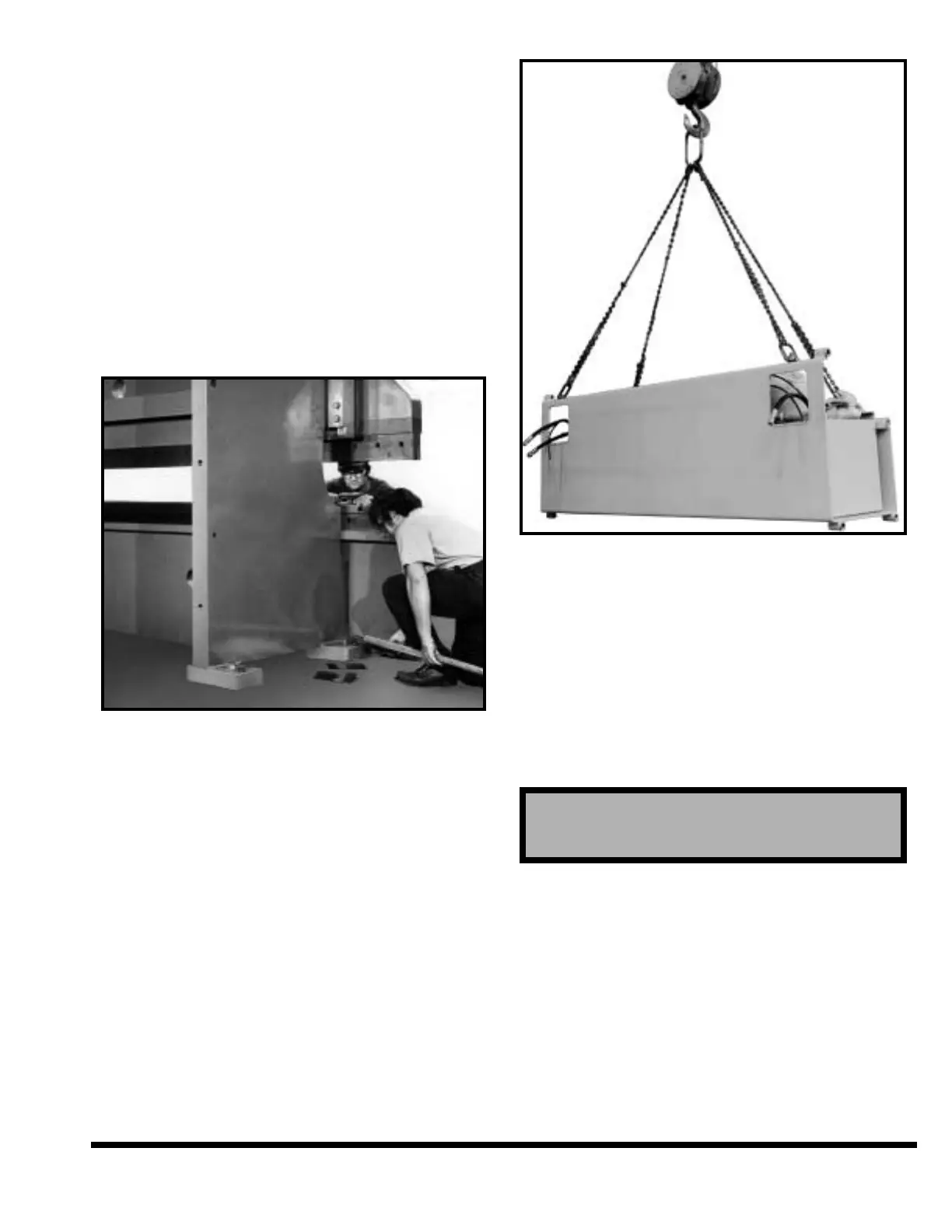
Install the housing brace and reservoir assembly.
To lift this unit use lifters and lifting holes as shown
in Figure 2-6.
FIGURE 2-6 – Lifting housing brace / reservoir
The housing brace acts as a spacer between the two
housings and is a close fit. Install housing brace
bolts and tighten securely. (See Figure 2-3.)
Thoroughly clean the front finished surfaces of both
ram slides and matching surfaces on rear of ram.
Use cleaning procedure previously described.
Remove ram bolts and dowel pins from tool box and
thoroughly clean. We recommend cooling dowel pins
(especially for 1000FM and larger) in dry ice for at
least two hours.
Grease both machined saddles of the ram with #2
EP lithium grease (C. I. grease H-2EP). Lift the ram
with a cable of sufficient capacity. Position ram
against front surface of ram slides. Line-up ram bolt
holes and dowel pin holes. Install ram bolts, but do
not tighten completely. Remove die clamps from ram
nose; clean and lightly oil all machined surfaces.
Discard wood shipping spacer. Replace the die
clamps on ram nose.
Adjust swivel-end guide bearing located on right ram
slide. Tighten both hex nuts equally, then back-off
1/4 turn. This will give .002" to .003" clearance.
CAUTION
Do not touch dry ice or cooled pins with bare hands.
Use gloves or other protective devices.
2-5