STEP REPT (Step Repeat): This value repre-
sents the number of times the ram will be cycled
for this step using the same reversal values each
stroke before continuing with the next step. The
default value of 1 indicates the step is only exe-
cuted once. This function allows two or more
identical program steps to be combined into one.
A value of zero will allow gage movement without
cycling the ram. The value before the ‘/’ indi-
cates the number of strokes remaining to com-
plete the step. The value after the ‘/’ is the total
number of repeats programmed.
Valid Range: 0 - 99
Default Value: 1
The following (FLNG DIM, R-AXIS, BEND AL, GA.
PAUSE, RETR DIS) will only be visible if an optional
backgage is installed.
FLNG DIM (Flange Dimension) (Optional):
This value is the desired position of an optional
X-axis backgage. The Flange dimension is the
distance between the center of the upper die and
the standard gaging surface of the backgage.
This value can also be entered by using the man-
ual GAGE JOG to position the backgage then
using the TRN key to transfer the actual gage
position into this field. Softkeys will appear when
this is the highlighted field to allow the backgage
to be jogged in or out. If the gage has not been
calibrated a “Gage Cal” softkey will appear in
place of the Jog keys.
Valid Range: 0.000 - X Max Dimension
Entry Format: XX.XXX English or XXXX.XX
Metric
Default Value: X Max Dimension -1”.
Gage Jog Softkeys: These softkeys allow manual
positioning of the backgage. Pressing and releas-
ing the key will move the gage by a small incre-
ment. Holding down the “Jog” key will begin
moving the gage in slow speed. After a few sec-
onds the gage will move in high speed. Releasing
the key will stop the gage movement. “Jog In”
moves the gage towards the die. “Jog Out” moves
the gage away from the die.
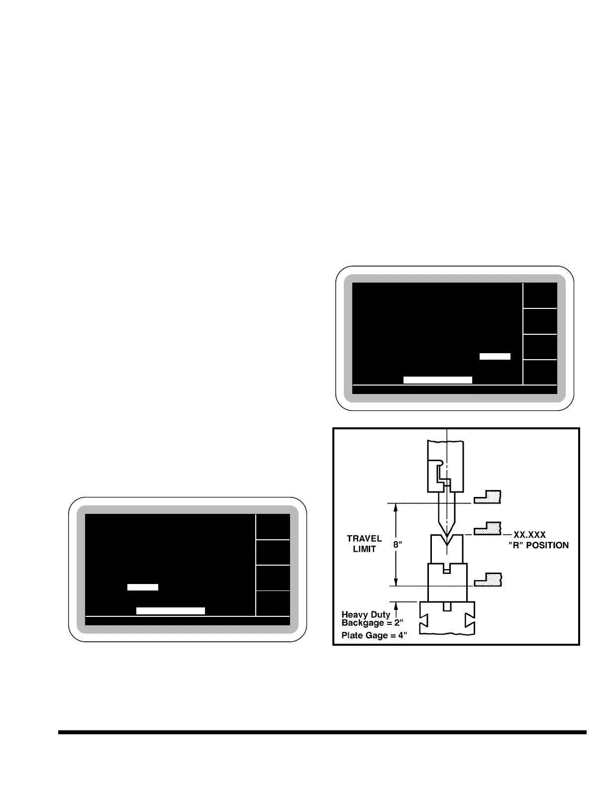
R-AXIS: This value is the desired position of an
optional programmable R-axis backgage. The
position is referenced to the bed. This value can
also be entered by using the manual GAGE JOG
to position the backgage then using the TRN key
to transfer the actual gage position into this
field. See Figure 7-4.
Valid Range: R Min. Dimension - R Max.
Dimension
Entry Format: XX.XXX English or XXX.XX
Metric
Default Value: R Max. Dimension
FIGURE 7-4 – R-Axis position
BEND AL (Bend Allowance): This value is
the allowance which is added to the actual
Flange Dimension value to determine the pro-
grammed gage position. If a bend allowance is
GA. PAUSE 0.1
GA. PAUSE 0.1