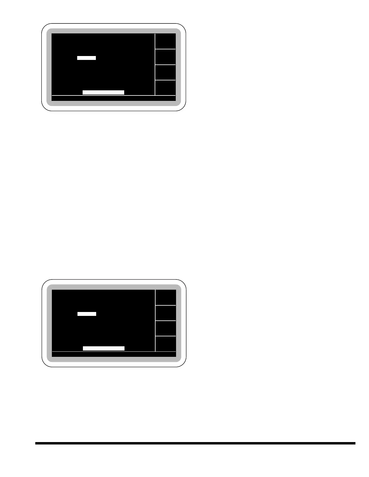
Values entered on the PROGRAM DATA screen
(with the exception of the Part Count and Batch
Counter) are entered on a per step basis. Each step
is independent of the others. The current step is
listed at the upper right portion of the screen.
When entering a new program the “Next Step” soft-
key will add a new step following the last step each
time it is pressed, and advance to that step. The
first step will always contain default values for all
fields. Following steps will copy the values entered
from the previous step. The first highlighted field
will be TOP STOP.
To display data for another step already entered,
use the field keys to move to the STEP field, key in
the desired step number and press ENT.
If ANGLE MODE is turned OFF in JOB DATA, the
DES ANGLE and ACT ANGLE fields will not be dis-
played as shown.
PART COUNT: This value can be edited for the
purpose of resetting it to zero or presetting the
counter. The counter is incremented by one each
time the control completes the last program step.
If the counter reaches 9999, it will roll over to 0
on the next part. (The part counter is not
affected by entering a new program or loading
a new program from internal memory.)
BATCH COUNT: The Batch Count Field is used
to set the number of times the program is run or
the number of parts in the batch. To make 100
parts, set the batch count to 100. Each time the
last step of the program is completed, the
counter will decrease by 1. When the batch
counter counts down to zero, the cycle will stop
and the status message “BATCH COMPLETE”
will be displayed. When the batch is completed,
the counter will automatically reset to its initial
previous programmed value. To disable the
batch counter and run continuously, set the
batch counter to zero.
TOP STOP: This field will automatically be high-
lighted when entering a new program. This field
is used to program the position where the ram
will stop at the top of the stroke. This value may
also be set by first positioning the Ram in SETUP
mode to the desired location, then selecting the
TOP STOP position field and pressing the TRN
key to transfer the actual ram position into the
field.
Valid Range: Closed Height - Open Height
Entry Format: XX.XXX English or XXX.XX Metric
Default Value: Open Height
DES ANGLE (Desired Angle): This value is
entered on a per step basis and is only used if
the ANGLE MODE is ON in JOB DATA. This field
will not be displayed otherwise. This value repre-
sents the included angle to be formed on this
step. After entering this value, the control will
immediately calculate a reversal position value
(not displayed) based on the tool, material and
top of material values entered in JOB DATA.
If the user enters a value in the DESIRED
ANGLE field, the value field for REVERSAL will
be blanked. By highlighting this field, pressing
ENT key will enter the default value of 90°.
Note: If the tool or material dimensions are
changed after the desired angle is
entered, the bottom reversal position will
be incorrect. The desired angle must be re-
entered after the correct tool and material
dimensions are entered.
Valid Range: Lower Vee Die Angle - 180°
Default Value: 90°
ACT ANGLE (Actual Angle): This value is
entered on a per step basis and is only used if
the ANGLE MODE is ON in JOB DATA. This field
will not be displayed otherwise. Once a bend has
been completed, the actual measured angle
(included angle), can be entered in this field if a
correction is required. The control will then cal-
culate a new reversal position (not displayed)
GA. PAUSE 0.1
GA. PAUSE 0.1