25-pin serial ports. Check the selected serial
port documentation to determine if any other
jumpers are required. If the PC has a 9-pin ser-
ial port and a 25-pin to 9-pin adapter cable is
used other than the 232CAMS cable, make sure
it is constructed according to Figure 9-16 and
includes all the handshake lines, in addition to
the TD RD and SG lines. Continue PC trou-
bleshooting in the Cable and Port Trou-
bleshooting section.
4.
If characters are displayed on the PC screen,
check the CINCINNATI control by connecting
the TDA and RDA wires together and connect-
ing the TDB and RDB wires together (refer to
Figure 9-18). Press the “Perform Test” softkey
on the FM. If the test fails, refer to the Cable
and Port Troubleshooting section.
Troubleshooting Optional Configuration (Figure 9-15)
1. If no characters are displayed on one or both of
the screens, isolate the PC from the control by
disconnecting the DB9M plug from the J9 con-
nector on the CPU board located inside the FM
control cabinet.
2. Check the PC by connecting a wire jumper from
TDA pin 3 to RDA pin 1 (refer to Figure 9-19).
Characters typed on the PC keyboard should
now be displayed on the PC screen.
3. If characters are not displayed, verify that a
jumper is installed from pin 4 to pin 5 and from
pins 6 and 8 to pin 20 on the DB25F connector,
and from pin 4 to pin 2 on the DB9M connector.
Check the selected serial port documentation to
determine if any other jumpers are required. If
the PC has a 9-pin serial port and a 25-pin to 9-
pin adapter cable is used other than the
232CAMS cable, make sure it is constructed
according to Figure 9-16 and includes all the
handshake lines, in addition to the TD RD and
SG lines. Verify that the cable is connected to
the actual port selected by the SET PORT com-
mand in the MSKERMIT.INI file.
If a third party serial port expansion board is
used, examine the board documentation care-
fully to ensure that any board jumpers or
switches are set correctly and that there are no
conflicts with serial ports on the mother board
or on other expansion boards. Continue PC
troubleshooting in the “Cable and Port Trou-
bleshooting” section.
Cable and Port Troubleshooting
1. Inspect the connectors for shorts and broken
wires and check for wiring errors by referring to
Figure 9-20 through 9-22 as a guide. For exam-
ple: when wiring or checking a DB25F connec-
tor for a PC 25-pin serial port, the pinout of the
wiring side of the connector is identical to the
front view of the DB25M serial port connector
shown in Figure 9-21.
2. Disconnect the cable at each end and use a
Volt Ohm Meter (VOM) or Digital Volt Ohm
Meter (DVOM) to check the cable for pin to
pin shorts, pin to ground shorts and end-to-
end wire continuity.
3. Use a VOM or DVOM to check for nominal ser-
ial port voltages. The voltages shown in Figure
9-20 for the CINCINNATI control are for the
unloaded condition (cable disconnected).
Unloaded voltages for the PC serial port pins
labeled input will typically be less than ±1 volt
and pins labeled output will be from 10 to 12
volts (Figure 9-21 and 9-22). The idle condition
for the TD pin is a negative voltage, changing to
a positive voltage while transmitting and hand-
shake lines like DTR and RTS will be negative
when inactive and positive when asserted.
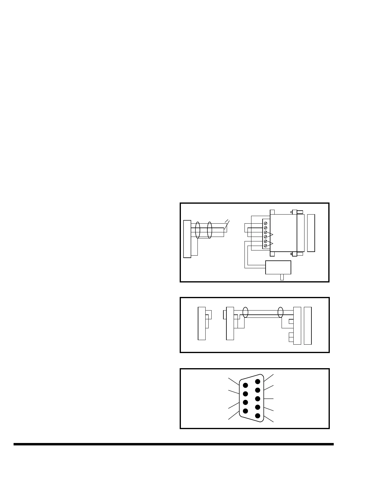
FIGURE 9-18 – Isolating Recommended Configuration
FIGURE 9-19 – Isolating the Optional Configuration
FIGURE 9-20 – FM Communication Port