3-9
Cisco 1240 Connected Grid Router Hardware Installation Guide
OL-26223-04
Chapter 3 Router Hardware Description
Router Overview
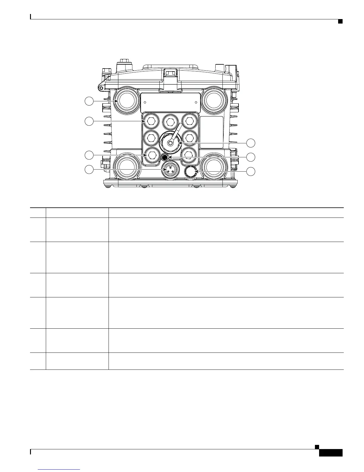
Figure 3-7 Router Base Exterior
Table 3-7 Router Base Exterior Features
Item Description Detailed Information
1 Antenna connectors (4) Install supported integrated or external antennas in these ports. For detailed information about
the router antennas and information about installation instructions, see the “Antennas”
chapter.
2 Cable ports (7) Use a cable glands to thread network cables through these ports when installing the router.
Unused ports are sealed with standard, environmental-proof plugs (3). For detailed
descriptions of supported cable glands and plugs, see the “Chassis Cable Ports” section on
page 3-13.
4 AC power connector Connect the router AC power connector to a power source to power on the router. For detailed
information about the connecting the router to the AC power supply, see the “AC Power
Supply” section on page 3-17.
5 10/100BASE-T Fast
Ethernet (FE) port
Use this connector to connect the router to a 10/100BASE-T Ethernet network without
requiring access to the router interior. This port is connected to the router ETH 2/5 port inside
the router chassis. For detailed information on connecting the router to an Ethernet network,
see the “Connecting the Ethernet Ports” section on page 6-21.
6 System (SYS) LED View the System LED to determine the overall operating and power status of the router. For
detailed information about all the route LEDs, see the “Router LED Locations and States”
chapter.
7 Protective vent The chassis vent relieves pressure buildup inside the router chassis. For a description of the
vent, see the “Protective Vent” section on page 3-17.
300538
1
5
6
7
2
3
4