5-21
Cisco 1240 Connected Grid Router Hardware Installation Guide
OL-26223-04
Chapter 5 Mounting the Router
Mounting Instructions
Step 4 Insert the three security panel screws (included in the mounting bracket kit) and tighten using the Phillips
screw driver. See Figure 5-18.
The router door captive bolt inside the door lock post is aligned over the bracket hole as shown in
Figure 5-19.
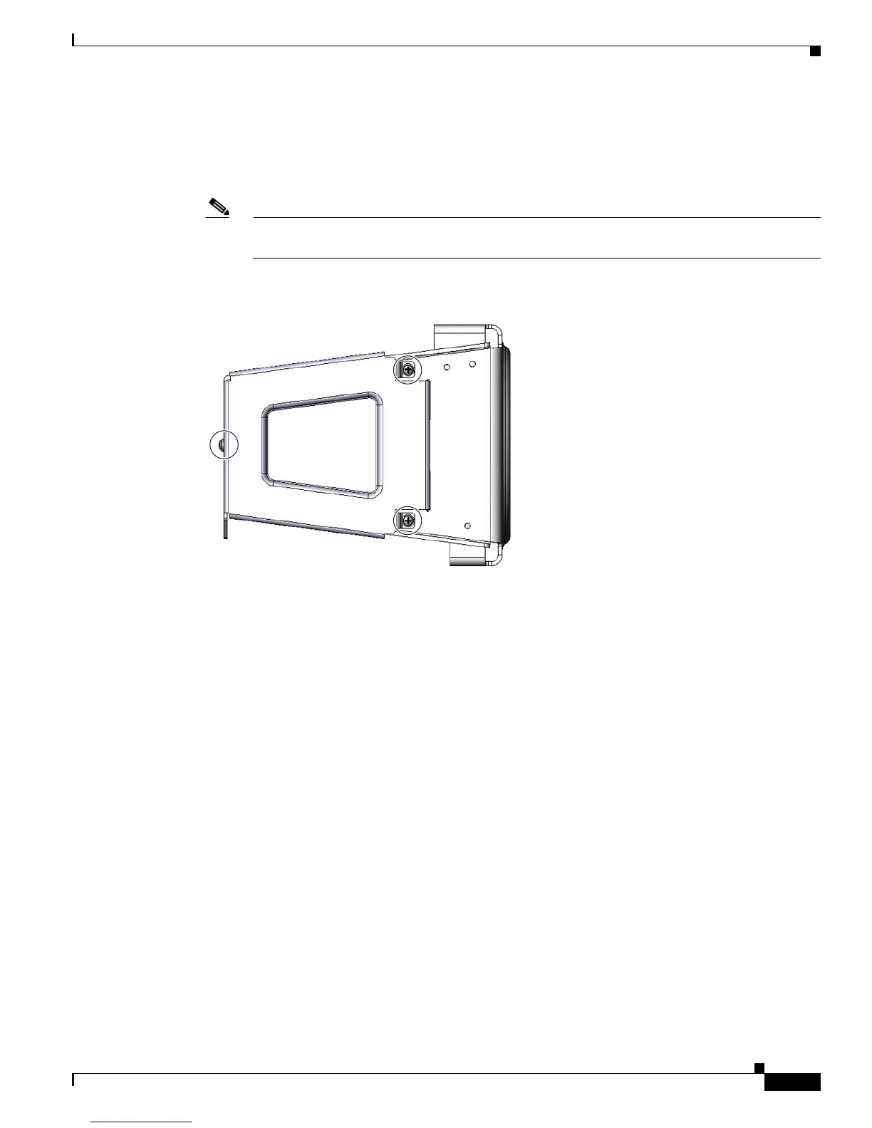
Note For clarity, the router is not shown here. During this procedure, the router will be mounted in the
bracket.
Figure 5-18 Security Panel Attached to Bracket with Included Screws
Step 5
Tighten the captive bolt (using 6-7 foot-pounds of torque) located inside the router door lock post
(
2 in Figure 5-19), ensuring the bolt extends into the security bracket (3 in Figure 5-19).
300619