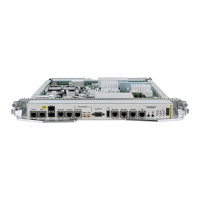
Satellite Chassis Management
The chassis level management of the satellite is done through the host because the satellite switch is a logical
portion of the overall virtual switch. This ensures that service providers get to manage a single logical device
with respect to all aspects including service-level, as well as box-level management. This simplifies the
network operations. These operations include inventory management, environmental sensor monitoring, and
fault/alarm monitoring for the satellite chassis through the corresponding CLI, SNMP, and XML interfaces
of the host Cisco ASR 9000 Series Router.
The satellite system hardware features, support for SFPs, and compatible topologies are described in the
Cisco ASR 9000 Series Aggregation Services Router Hardware Installation Guide.
Note
All the SNMP features supported on the Cisco ASR 9000 Series router is supported for satellite. For more
information, see Cisco ASR 9000 Series Aggregation Services Router MIB Specification Guide.
Note
ARP Redundancy Support for Dual Head Topology
The Address Resolution Protocol(ARP) redundancy support feature allows you to synchronize the ARP table
entries between the active and standby hosts in a dual home Satellite nV System topology. In the Dual Head
Satellite nV System topology, all satellite traffic flows to one host router (active host) and therefore all ARP
entries reside on the active host. When the active host goes down, the standby host needs to rebuild the ARP
table. But with a large number of devices, this can take a significant amount of time, impacting the network
uptime. The process of synchronizing the ARP database between the active and standby hosts can reduce this
downtime. The synchronization happens as and when a new entry is learnt or when the active host goes down.
There is no specific frequency for synchronization. You can also pause or restart the synchronization process
whenever required.
The ARP database is distributed across all the nodes (RP/LC) in the router. The ARP entries are programmed
for an interface only in the node where the data plane is replicated. In case of virtual interfaces (like
Bundle-Ether, BVI and so on), where the control plane is located in RP, the ARP entries are programmed
only in the line cards wherever the data plane is replicated. The RP would have entries only for the physical
interfaces that have its control plane in RP like Management interfaces. The Txlist infrastructure library
facilitates the ARP table entries synchronization process to happen. The ARP table has three key entries,
which are the IPv4 address, MAC address, and the corresponding interface.
The current architecture can support only two host nodes in a redundancy group. But a specific host router
can be part of multiple redundancy groups. This is a sample configuration for ARP synchronization.
group <id-number>
peer <neighbor ipv4 address>
source-interface <interface-name>
interface-list
interface <interface-name to be synced> id <unique-id>
!
!
!
You can use the show arp redundancy summary location command to display the summary of entries.
Cisco ASR 9000 Series Aggregation Services Router nV System Configuration Guide, Release 5.3.x
28
Configuring the Satellite Network Virtualization (nV) System
Satellite Chassis Management

 Loading...


