16-22
Catalyst 2950 and Catalyst 2955 Switch Software Configuration Guide
78-11380-12
Chapter 16 Configuring VLANs
Configuring VLAN Trunks
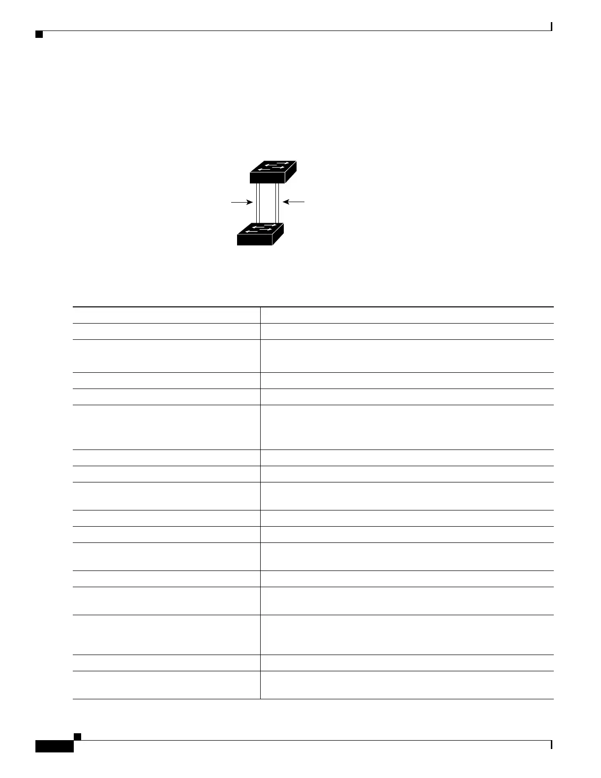
In this way, Trunk 1 carries traffic for VLANs 8 through 10, and Trunk 2 carries traffic for VLANs 3
through 6. If the active trunk fails, the trunk with the lower priority takes over and carries the traffic for
all of the VLANs. No duplication of traffic occurs over any trunk port.
Figure 16-3 Load Sharing by Using STP Port Priorities
Beginning in privileged EXEC mode, follow these steps to configure the network shown in Figure 16-3.
93370
Switch A
Switch B
Trunk 2
VLANs 3 – 6 (priority 16)
VLANs 8 – 10 (priority 128)
Trunk 1
VLANs 8 – 10 (priority 16)
VLANs 3 – 6 (priority 128)
Command Purpose
Step 1
configure terminal Enter global configuration mode on Switch 1.
Step 2
vtp domain domain-name Configure a VTP administrative domain.
The domain name can be from 1 to 32 characters.
Step 3
vtp mode server Configure Switch 1 as the VTP server.
Step 4
end Return to privileged EXEC mode.
Step 5
show vtp status Verify the VTP configuration on both Switch A and Switch B.
In the display, check the VTP Operating Mode and the VTP Domain
Name fields.
Step 6
show vlan Verify that the VLANs exist in the database on Switch A.
Step 7
configure terminal Enter global configuration mode.
Step 8
interface fastethernet 0/1 Enter interface configuration mode, and define Fast Ethernet port 0/1
as the interface to be configured as a trunk.
Step 9
switchport mode trunk Configure the port as a trunk port.
Step 10
end Return to privilege EXEC mode.
Step 11
show interfaces fastethernet
0/1switchport
Verify the VLAN configuration.
Step 12
Repeat Steps 7 through 11 on Switch A for Fast Ethernet port 0/2.
Step 13
Repeat Steps 7 through 11 on Switch B to configure the trunk ports on
Fast Ethernet ports 0/1 and 0/2.
Step 14
show vlan When the trunk links come up, VTP passes the VTP and VLAN
information to Switch B. Verify that Switch B has learned the VLAN
configuration.
Step 15
configure terminal Enter global configuration mode on Switch A.
Step 16
interface fastethernet 0/1 Enter interface configuration mode, and define the interface to set the
STP port priority.