2-35
Cisco ONS 15310-MA SDH Troubleshooting Guide, Release 9.0
78-18663-01
Chapter 2 Alarm Troubleshooting
Alarm Procedures
Step 14 If the alarm does not clear, complete the “Physically Replace a Card” procedure on page 2-153 for the
Ethernet card.
Note When you replace a card with the identical type of card, you do not need to make any changes
to the database.
Step 15 If the alarm does not clear, log into the Technical Support Website at
http://www.cisco.com/cisco/web/support/index.html for more information or call Cisco TAC
(1-800-553-2447) in order to report a Service-Affecting (SA) problem.
2.7.31 CARLOSS (EQPT)
Default Severity: Major (MJ), Service-Affecting (SA)
SDH Logical Object: EQPT
A Carrier Loss on the LAN Equipment alarm generally occurs on STM1 and STM4 ports when the
ONS 15310-MA SDH and the workstation hosting CTC do not have a TCP/IP connection. The problem
involves the LAN or data circuit used by the LAN (RJ-45) connector on the system. The CARLOSS
alarm does not involve an Ethernet circuit connected to an Ethernet port. The problem is in the
connection and not CTC or the node.
Warning
Invisible laser radiation could be emitted from the end of the unterminated fiber cable or connector.
Do not stare into the beam directly with optical instruments. Viewing the laser output with certain
optical instruments (for example, eye loupes, magnifiers, and microscopes) within a distance of
100 mm could pose an eye hazard.
Statement 1056
Warning
Use of controls, adjustments, or performing procedures other than those specified could result in
hazardous radiation exposure.
Statement 1057
Clear the CARLOSS (EQPT) Alarm
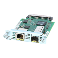
Step 1 If the reporting entity is a pluggable port module (PPM) port, confirm that the PPM is correctly
configured by completing the following steps:
a. Double-click the controller card (ONS 15310-MA SDH).
b. Click the Provisioning > Pluggable Port Modules tabs.
c. View the Pluggable Port Modules area port listing in the Actual Eqpt Type column and compare
this with the contents of the Selected PPM area Rate column for the port.
d. If the rate does not match the actual equipment, you must delete and recreate the selected PPM.
Select the PPM, click Delete, then click Create and choose the correct rate for the port rate.
Step 2 If the reporting port is an STM1 or STM4 port, verify connectivity by pinging the node that is reporting
the alarm by completing the procedure in the “1.8.8 Verify Microsoft Windows PC Connection to the
Node (Ping)” section on page 1-60.
 Loading...