Page 12 399G169 Rev B 27 April 2016
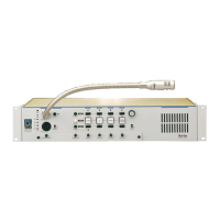
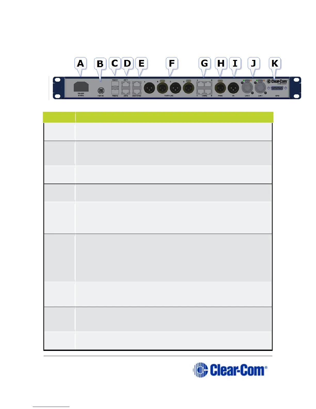
2.4 FreeSpeak II Base rear connectors
Power connector. Mains power lead with internal current
converter.
Power connector. DC wallwart power lead (Part # 453G032, 12V
DC, 60W). Use connector A or connector B or both to guard
Fiber connector to FS II splitter (Part # FSII-SPL). Used with Fiber
module (Part # HCI-SMFO or MMFO)
RJ45 connector to antenna (FSII-TCVR-19, FSII-TCVR-24) or
splitter.
DECT Sync. RJ45 connector to another Base Station. Can also be
used to synchronize to other Clear-Com DECT devices. In some
cases, you will need a cross-over cable instead of a standard
XLR Partyline connectors (standard microphone cable). Note: If
power is enabled on these ports the power operates across a pair
of ports, A and B, C and D.
Be sure to null the ports whenever cabling arrangements are
changed.
RJ45 connectors for 4-wire intercom. These ports can change pin
polarity according to whether they are connecting to a matrix or
XLR connector (standard microphone cable) for Program Feed
input, typically from a mixing console or audio player. Adjust
levels in Audio Settings/Program Input in the Base Station menus.
XLR connector (standard microphone cable) for Stage Announce
output.