833-3577 CB-FALCON SYSTEM OPERATOR INTERFACE
750-241 31 65-0296—01
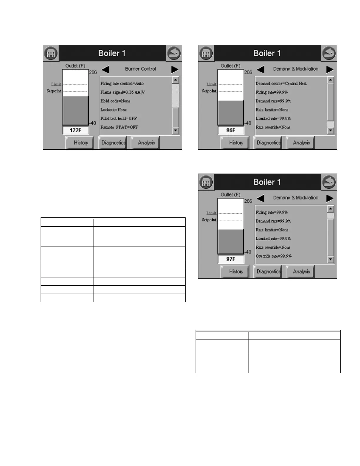
Fig. 70. Burner Control Status menu (bottom).
Burner control can be turned on and off in the 833-3639 by the
user.
Table 28 displays the status page data for 833-3639 demand
and modulation.
The bar graph displayed for this status is the outlet sensor
temperature.
Fig. 71. Demand and Modulation Status menu (top).
Fig. 72. Demand and Modulation Status menu (bottom).
Table 28 displays the status page data for 833-3639 inlet
temperature.
The bar graph displayed for this status is the inlet sensor
temperature.
Table 27. Demand and Modulation Status.
Data Comment
Demand source CH, DHW, Lead Lag, or Frost
Protection (parameter that has current
priority)
Firing rate % or RPM. Adjustable when firing rate
control set to Manual.
Demand rate % or RPM.
Rate limit % or RPM, or None
Limited rate % or RPM
Rate override Disable or Enable Rate Override
Override rate % or RPM
Table 28. Inlet High Limit Status.
Data Comment
Inlet temperature Inlet sensor temperature (same as bar
graph)
Inlet sensor state None, Monitor, Blocked, Lockout,
Open, Short, or Alarm (None=no inlet
sensor)