INSTALLATION MANUAL
CMA-5024 GLSSU
This document includes Proprietary Information and shall not be reproduced or communicated to third party
without prior written permission by CMC Electronics Inc.
Page A.29
Revision 1 Jan 19, 2009
The Time Mark signal consists of a 1-millisecond pulse with a nominal period of one second. Its rising
edge (line "Hi" voltage becoming negative with respect to line "Lo" at the J1 connector pins) tags within
±2 microseconds the epoch at which the navigation data, broadcasted following the pulse on the
ARINC 429 output busses, were actually sampled by the GLSSU. This accuracy specification applies
when the GLSSU is in the Navigation mode with SA inactive and TDOP < 0.8.
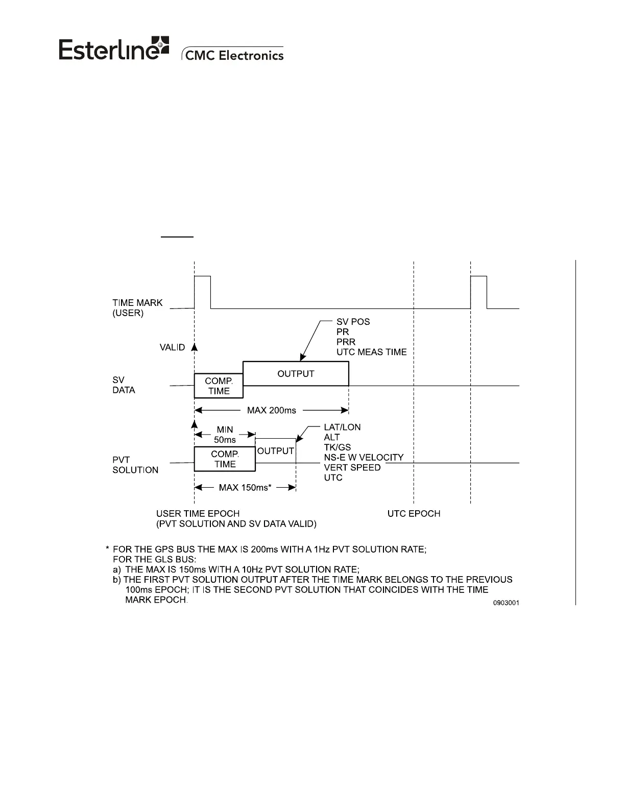
The timing relationship between ARINC 429 data outputs and Time Mark outputs from the GLSSU is
defined in Figure A-10 below. The ARINC 429 data output labels 150,140 and 141 broadcast the UTC
time of the epoch at which the navigation data were actually sampled by the GLSSU.
The GLS bus outputs the PVT solution data at a 10 Hz rate -10 data samples per Time Mark period- so
that, due to internal processing delays, there is a timing ambiguity: As illustrated, the Time Mark
relates to the second
set of PVT data outputs following the pulse. The GPS bus data and the SV data
are output at a 1 Hz rate so that there is no such ambiguity.
The Time Mark pulse output begins within 5 seconds after self-test completion, following power-up or
initiated self-testing.
The document reference is online, please check the correspondence between the online documentation and the printed version.

 Loading...