INSTALLATION MANUAL
CMA-5024 GLSSU
This document includes Proprietary Information and shall not be reproduced or communicated to third party
without prior written permission by CMC Electronics Inc.
Page 119
November 21, 2008
(2) Install attachments per Original Equipment Manufacturer's (OEM) Structural Repair Manual (SRM).
(3) To provide a good grounding to the aircraft, remove all paint and primer on both sides of skin
mounting area.
(4) Finish all aluminum parts with Alodine 1200, dip or brush method.
(5) Follow the manufacturer instructions for mounting and fastening the antenna on the aircraft.
CAUTION: TO PREVENT DAMAGE TO THE ANTENNA AND/OR TO THE AIRFRAME,
TIGHTEN THE ANTENNA MOUNTING HARDWARE WITHIN THE SPECIFIED
TORQUE LIMITS.
(6) Ensure that the proper gasket (O-ring) is installed into the groove provided on the antenna.
(7) Ensure that the joint between antenna and fuselage skin is sealed. Remove any excess sealant.
Note: For applications where resistance to Trichloroethane (1.1.1) is required, a sealant
such as Dow-Corning 730 is recommended. For other applications, RN 10-16 or
equivalent may be suitable.
(8) Ensure that antenna case and its fasteners are electrically bonded to the airframe, so that the
resistance to the aircraft metal skin does not exceed .0025 ohms.
CAUTION: PROPER BONDING OF THE GPS ANTENNA VIA ITS MOUNTING SCREWS
AND NUTS IS ESSENTIAL FOR LIGHTNING PROTECTION.
(9) Ensure that the RF antenna cable connector is plugged onto connector J1 on the antenna proper. It
should be secured using a safety wire.
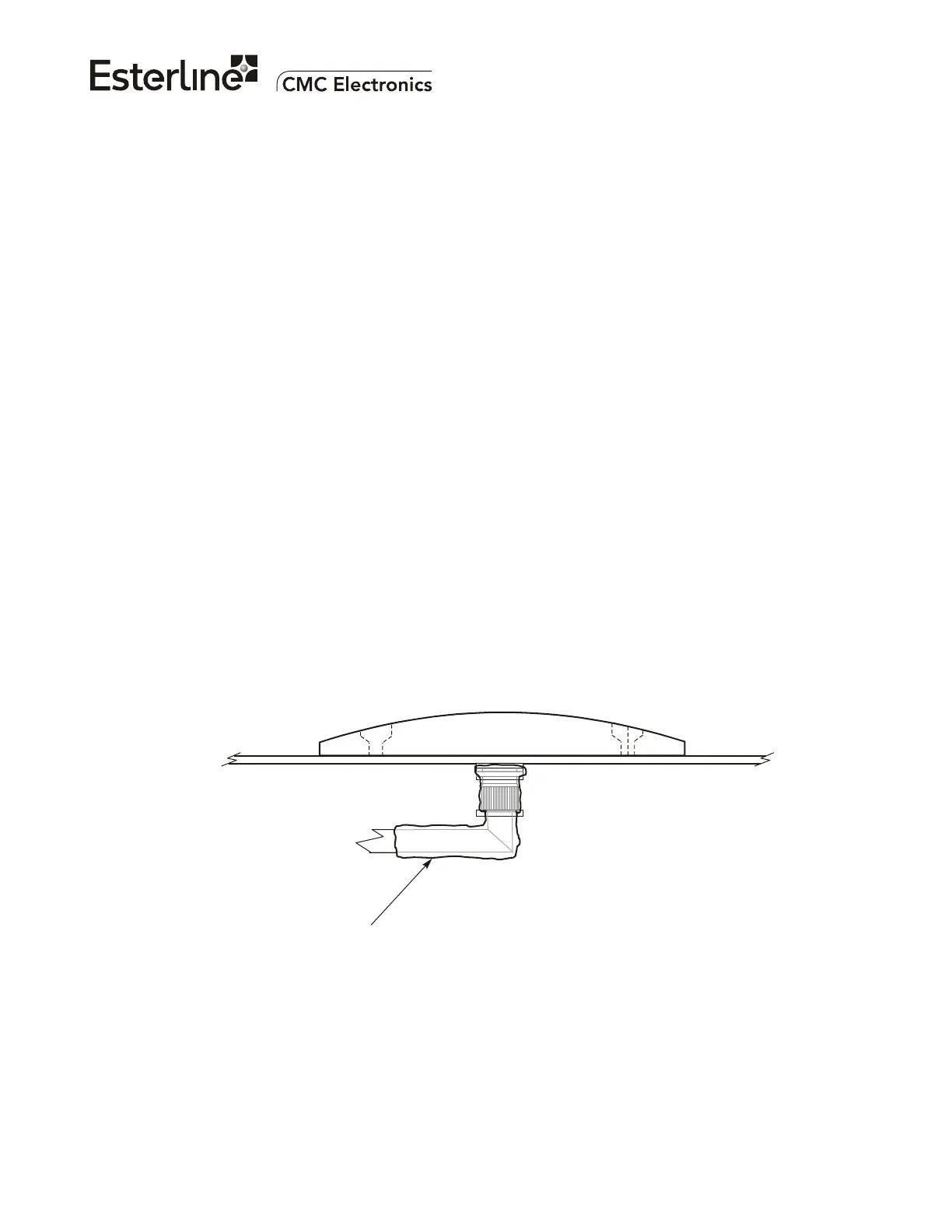
Note: To prevent water from seeping into the antenna through the antenna coaxial cable
connector, a sleeving such as adhesive heat shrink tubing (Refer to Figure 111)
should be used to cover the connector body.
412
11
ADHESIVE HEAT SHRINK TUBING
Figure 111. Antenna Coaxial Connector Sleeving
The document reference is online, please check the correspondence between the online documentation and the printed version.

 Loading...