INSTALLATION MANUAL
CMA-5024 GLSSU
This document includes Proprietary Information and shall not be reproduced or communicated to third party
without prior written permission by CMC Electronics Inc.
Page 111
November 21, 2008
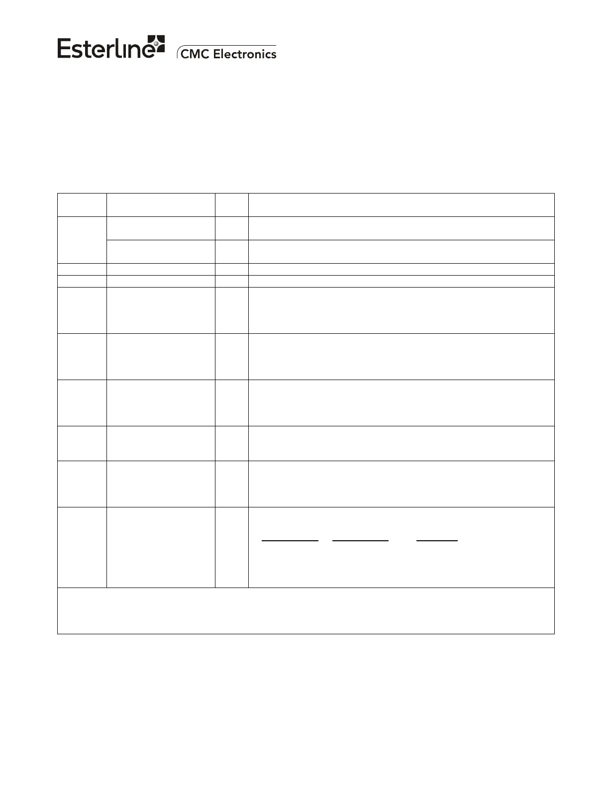
Figure 106 provides pin assignments and system interwiring information. Refer to Appendix A for a
detailed signal description.
A 2.5 A minimum circuit breaker should protect the +28 VDC power input line at J1-35. All
ARINC 429/419 serial data bus and Time Mark lines must use twisted-shielded cables, and their shields
must be grounded at both ends.
The power input (at pins J1-35 & J1-34) is DC-isolated from the chassis ground and will withstand
accidental polarity reversals without damage.
PLUG
PIN NO.
FUNCTION I/O REMARKS
+28 VDC supply I Connect to positive side of aircraft DC power supply through a
circuit breaker. Normal operating voltage is +22 to +36 VDC.
J1-35
J1-34
+28 VDC Return I Connect to negative side of aircraft DC power supply. The Return
is isolated from chassis ground.
J1-33 Chassis Ground GND Connect to good aircraft ground.
J1-8 Input Discrete Return GND Common ground connection for discrete signals.
J1-1 GLSSU Fault Discrete O Contact closure to ground; rating: 280 mADC & 36 VDC max
Open: GLSSU is operational.
Closed / Short to ground: GLSSU is non-operational (fault).
J1-12 Data Loader Input
Discrete
I Open (no connection)/Grounded (at J1-8) input discrete:
Open: Operation normal
Ground: GLSSU DATA LOAD Mode allowed
J1-21 * 429 HS/LS Select
Input Discrete
I Open (no connection)/Grounded (at J1-8) input discrete
Open: ARINC 429 “GPS bus” outputs set to high speed
Ground: ARINC 429 “GPS bus” outputs set to low speed
J1-28 Air/Ground Input
Discrete
I Open/Grounded input discrete, normally connected to the Weight-
On-Wheels aircraft signal. Polarity set by the Air/Ground Discrete
Open In Air APD parameter
J1-40 * DADS 419/429 Select
Input Discrete
I Open (no connection)/Grounded (at J1-8) input discrete:
Open: Accept ARINC 429 on DADS/FMS inputs
Ground: Accept ARINC 419 DADS on DADS/FMS inputs
J1-36 *
J1-5 *
SDI Pin No.1
SDI Pin No.2
Input Discretes
I
I
Open (no connection)/Grounded (at J1-8) input discretes:
SDI pin No.2
SDI pin No.1 IDENT***
Open Open Do NOT use (00) **
Open Gnd Unit No.1 (01)
Gnd Open Unit No.2 (10)
Gnd Gnd Unit No.3 (11)
* The GLSSU reads the state of these discrete input signals only during Self-Test mode (power-up and
initiated).
** The GLSSU must not be installed with both SDI inputs ungrounded.
*** The settings must match the SDI defined in the selected APD Configuration; refer to Appendix E
Figure 106. Pin Assignments (Sheet 1 of 2)
The document reference is online, please check the correspondence between the online documentation and the printed version.

 Loading...