INSTALLATION MANUAL
CMA-5024 GLSSU
This document includes Proprietary Information and shall not be reproduced or communicated to third party
without prior written permission by CMC Electronics Inc.
Page C.6
November 21, 2008
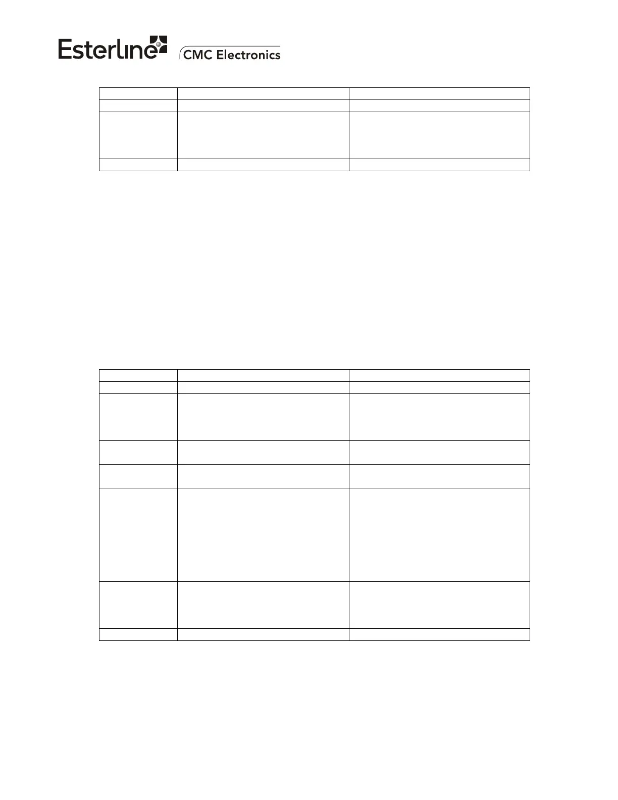
ARINC BIT DESCRIPTION SETTING
Slot Group H = 111
10 - 9 SDI All Call = 00
Unit 1 = 01
Unit 2 = 10
Unit 3 = 11
8-1 Octal Label 045
Note 1: When the ARINC word is transmitted by the GLSSU, Slot Group A is used to indicate that the
message block originates from the GLSSU (i.e., it is not re-transmitting a message block
received from a Controller Unit or X-Talk input).
Note 2: When the ARINC word is transmitted by the GLSSU, Slot Group B is used to indicate that the
GLSSU is re-transmitting a message block received from a Controller Unit or X-Talk input.
This code is intended for Controller Units, so that they identify the receipt of cross-talk
messages.
Note 3: The GLSSU can accept one input message per second, maximum. If multiple messages are
received within the response time, the GLSSU will process only the first and will ignore the
subsequent ones for up to one second.
1.11 Label 046 - Message Block Body - Input/Output
Refer to Appendix G for a sample FAS data block output.
ARINC BIT DESCRIPTION SETTING
32 Parity Odd
31-30 SSM Normal Operation = 00
No Computed Data = 01
Functional Test = 10
Fail Warning = 11
29 - 22 Second Data Message Byte
(MSB..LSB)
21 - 14 First Data Message Byte
(MSB..LSB)
13 - 11 Station Slot Identifier
(see Note)
Slot Group A = 000
Slot Group B = 001
Slot Group C = 010
Slot Group D = 011
Slot Group E = 100
Slot Group F = 101
Slot Group G = 110
Slot Group H = 111
10 - 9 SDI All Call = 00
Unit 1 = 01
Unit 2 = 10
Unit 3 = 11
8-1 Octal Label 046
Note: Refer to Notes 1, 2 and 3 of label 045.
The document reference is online, please check the correspondence between the online documentation and the printed version.

 Loading...