INSTALLATION MANUAL
CMA-5024 GLSSU
This document includes Proprietary Information and shall not be reproduced or communicated to third party
without prior written permission by CMC Electronics Inc.
Page 301
November 21, 2008
SECTION IV
REMOVAL
1. GENERAL
This section contains removal procedures for the GLSSU and antenna. Refer to outline drawings in Section
II for location of screws, holes and plugs.
A. GLSSU
Pull the proper power circuit breakers to ensure that the power to the GLSSU is off.
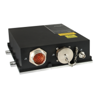
Disconnect the aircraft wiring cable to J1, the antenna coaxial cable to J2.
Remove the four mounting screws from the mounting plate of the GLSSU.
Pull the GLSSU away. Clean the mounting area and the connectors, removing the traces of corrosion.
B. GPS Antenna
Pull the proper power circuit breakers to ensure that the power to the GLSSU is off.
Disconnect the antenna coaxial cable on the GPS antenna and free its safety wire if installed.
Loosen and remove four No. 10-100° FHMS screws or the equivalent.
Break or pry loose the seal between antenna case and aircraft skin; making sure not to damage either.
Remove the GPS antenna and clean the mounting area, removing the traces of sealant and corrosion
including on the antenna and cable connectors. The antenna O-ring gasket may need cleaning and
replacing.
The document reference is online, please check the correspondence between the online documentation and the printed version.

 Loading...