INSTALLATION MANUAL
CMA-5024 GLSSU
This document includes Proprietary Information and shall not be reproduced or communicated to third party
without prior written permission by CMC Electronics Inc.
Page 106
November 21, 2008
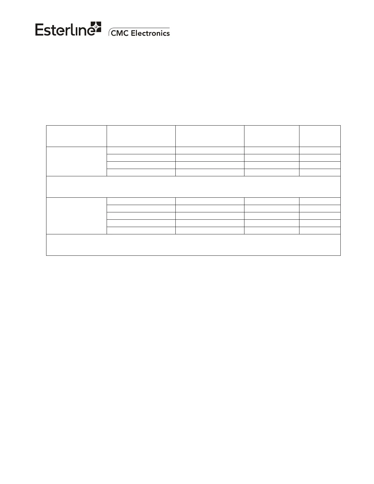
B. RF Cable Type and Suppliers
The RF cables must be coaxial with a nominal characteristic impedance of 50 ohms. The tolerance on
the impedance should be ±3 % or better.
CMC strongly recommends using coaxial cables built with double-braid or triple-braid shields since more
immune to EMI. The complete cable assembly (connectors and cable) should be purchased from one of
the selected vendors listed in the table below to ensure of high integrity connections. The cables should
be Skydrol-proof and low smoke, flame retardant types. At the time of ordering, a copy of the cable test
results and a certificate of conformity should be required as part of the installation certification process.
MANUFACTURER
MANUFACTURER
PART NUMBER
NOMINAL LOSS PER
100 FEET @ 1.5 GHZ
TNC
STRAIGHT
PLUG
TNC
90° PLUG
310801 4.4 dB CTS022 CTR022
311201 6.5 dB CTS122 CTR122
311501 8.63 dB CTS122 CTR122
E.C.S.
311601 10.6 dB CTS922 CTR922
All ECS connectors are dual crimp using standard MIL-C-22520 tools.
E.C.S. (Electronic Cable Specialists), 5300 W. Franklin Drive, Franklin, WI 53132
Telephone: 1-800-327-9473 or (414) 421-5300
S22089 4.8 dB 190408 190409
T556124 7.1 dB 190208 190209
S55122 7.1 dB 190608 190609
S33141 8.6 dB 190308 190309
PIC wire & cable
S67163 10 dB 190508 190509
PIC connectors are waterproofed and assemblies are traceable by serial numbers
PIC Wire & Cable, N63 W22619 Main Street, P.O. Box 330, Sussex, WI 53089-0330
Telephone: 1-800-742-3191 or (414) 246-0500 Fax: (414) 246-0450
The bigger cables have lower losses and are mechanically more sturdy and durable, however they are
costlier, heavier, more rigid hence more difficult to install.
C. Cable length limits
The overall cable insertion loss must be controlled as follows in order to prevent either signal-to-noise
ratio degradation, or overloading of the receiver in the GLSSU; referring to Figure 103:
(1) The minimum cable loss (Lmin of Figure 103) at 1.575 GHz between the Low Noise Amplifier (LNA)
output (antenna RF connector) and the GLSSU RF input connector (J2) is equal to the maximum
antenna preamplifier gain (from manufacturer specifications) minus 33 dB.
(2) The maximum cable loss (L
max of Figure 103) at 1.575 GHz between the active antenna output and
the GNSSU RF input connector (J2) is equal to the minimum antenna preamplifier gain (from
manufacturer specifications) minus 13.5 dB minus the 1 dB allocation for VSWR and other parasitic
losses. The allocation for each RF connector pair is accounted for separately based on the number
of interconnections in the installation.
The document reference is online, please check the correspondence between the online documentation and the printed version.

 Loading...