INSTALLATION MANUAL
CMA-5024 GLSSU
This document includes Proprietary Information and shall not be reproduced or communicated to third party
without prior written permission by CMC Electronics Inc.
Page E.2
November 21, 2008
1.1 BLANK APD FORMS
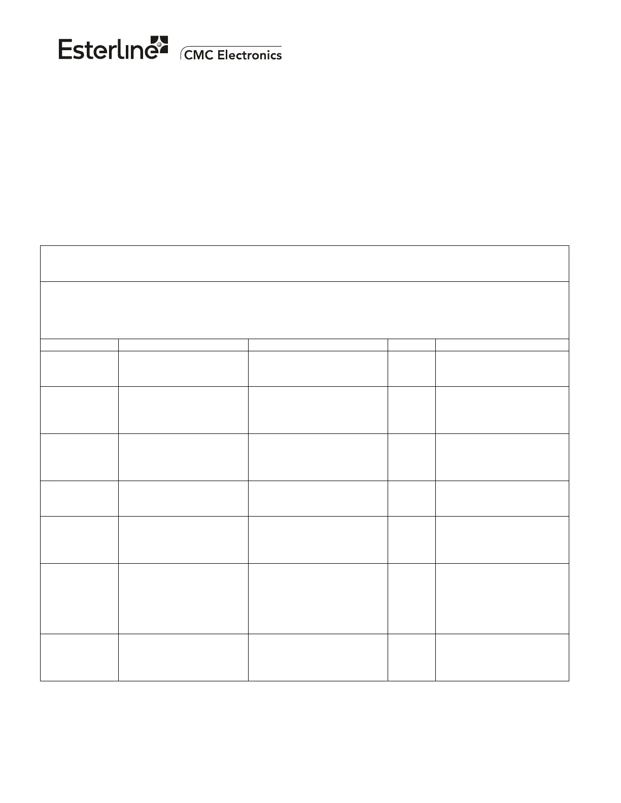
This section contains a blank template of 5 tables required for defining a custom APD Configuration.
Refer to section 3 for a detailed description of each APD parameter. A single APD File can contain from
one to sixteen APD Configurations; each one must be assigned a consecutive number from 0 to 15.
The APD CID part-number and the GLSSU part-number variations are shown "XXX"; do not fill them
since they will be assigned by CMC, after the processing of the request to create a new APD File.
Note that the APD Parity Discrete Check APD parameter must be same for all APD Configurations in
the APD File.
APD CID part number: 169-615462-XXX
APD Configuration number: ____
Description/intended usage (for reference only):
___________________________________________________________________________________________
___________________________________________________________________________________________
_________________________________________________________________________
Parameter When Enabled (On) When Disabled (Off) Setting Notes
APD Parity
Discrete Check
The APD Select Parity
Discrete Input is used.
The APD Select Parity
Discrete Input is not used.
Must be same for all APD
Configurations in the APD
File.
HIS Input
Power
HIS Input Power
connected to the same
power source as the
GLSSU +28 Volt.
HIS Input Power not
connected or connected to a
different power source than
the GLSSU +28 Volt.
Synchronized
Approach
Selection
Synchronize approach
selection among GLSSUs.
Controller Units provide
synchronization as
appropriate to the
installation.
Reset on
Critical Fault
Allows a hardware reset
following a Critical Fault.
Remains in Fault Mode
indefinitely following a
Critical Fault.
Navigation
Center Position
Output on GLS
bus
Output position labels
correspond to the aircraft
navigation center position.
Output position labels
correspond to the GPS
antenna position.
Attitude Data
Used
Pitch & roll & true heading
from the IRS inputs is
required for the navigation
center computation.
Navigation center
computation uses a roll of
zero, a heading per the FAS
Runway Heading, and a
pitch per Default Aircraft
Pitch APD.
Cross-Check Enables the Cross-Check
of the position computation
against that of the off-side
GLSSU(s).
Position Cross-Check
disabled.
The document reference is online, please check the correspondence between the online documentation and the printed version.

 Loading...