INSTALLATION MANUAL
CMA-5024 GLSSU
This document includes Proprietary Information and shall not be reproduced or communicated to third party
without prior written permission by CMC Electronics Inc.
Page 16
November 21, 2008
Figure 6. Typical retrofitted dual GLSSU ARINC743A-4 installation
G. GLSSU Mechanical Description
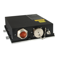
Refer to the picture of the equipment, Figure 1, and to the GLSSU block diagram in Figure 7. The
outline drawing is given in Section II Figure 104.
The GLSSU consists in a Core Receiver Assembly (CRA) mounted within an aluminum housing,
together with two power supply modules and an interconnect assembly that carries the large round
aircraft connectors J1 and J3 bolted on the GLSSU frame.
The GPS/SBAS antenna connects to the CRA via the TNC coaxial cable connector J2 on the frame.
The CRA consists of a printed Circuit Card Assembly (CCA) housing a complete 24 channel GPS
receiver plus a High Integrity Switch (HIS).
The document reference is online, please check the correspondence between the online documentation and the printed version.

 Loading...