INSTALLATION MANUAL
CMA-5024 GLSSU
This document includes Proprietary Information and shall not be reproduced or communicated to third party
without prior written permission by CMC Electronics Inc.
Page 108
November 21, 2008
5. OUTLINE DRAWINGS
A. GLSSU Outline
The outline drawing in Figure 104 gives the dimensional, mounting and physical data required for
installation of the GLSSU in the aircraft. Refer to paragraph 9 of this section for detailed installation
instructions.
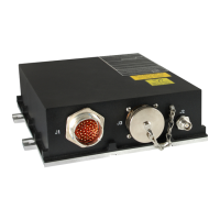
The large 41-pins male round connector socket labeled 'J1' on the front face mates with a female cable
connector plug type M83723/77R2041N. The small female coaxial connector socket, labeled 'J2' on the
front face, mates with any commercially available male TNC cable connector plug.
The large 100-pins male round connector socket labeled 'J3' on the front face mates with a female cable
connector plug type MS27473E22F35S.
Note: When the cable connector on J3 is not engaged, J3 must be protected from contamination
using the protective metal cap chained to the GLSSU frame (not shown in outline drawing
below). When the cable connector is engaged on J3, the protective metal cap must be
securely tied to the cable.
The document reference is online, please check the correspondence between the online documentation and the printed version.

 Loading...