INSTALLATION MANUAL
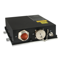
CMA-5024 GLSSU
This document includes Proprietary Information and shall not be reproduced or communicated to third party
without prior written permission by CMC Electronics Inc.
Page 7
November 21, 2008
6. EQUIPMENT DESCRIPTION
A. Typical Installations without ILS/DME look-alike data bus interfaces
The typical aircraft installation consists of two GLSSUs interconnected with a Flight Management
Systems (FMS) and an Electronic Display Systems (EDS) in the cockpit as illustrated Figure 3 and
Figure 4, respectively for Class Beta-3 and Class Delta-4 equipment. A similar design applies for single
and triple installations. Refer to Section I 6 F for a typical retrofit installation that only implements Class
Beta-1 functions.
The figures illustrate the left or right side of the aircraft installation. Each GLSSU is connected to its own
antenna, typically but not necessarily close to each other. The antenna is powered by a DC supply in
the GLSSU.
In the figures, the dotted lines joining the two GLSSU illustrate an optional ARINC 429 "cross-talk"
interconnection that can provide automatic data “cross-loading” and position “cross-check”, if so
enabled by the APD Configuration. Refer to the Synchronized Approach Selection and Cross-Check
APD parameters in Appendix E. In a typical installation, the FMS will provide both functions and these
APD parameters will be disabled. The second cross-talk input bus of each GLSSU allows
interconnecting a third unit in a triple installation.
Refer to the installation restrictions and recommendations in subsection C below,
Note: The requirement for the cross-talk interconnection will be determined by the system
integrator, based on the system safety assessment and on the capability of the on-board
Controller Units.
Note: A failure of the position cross-check will only activate the failure flags on the deviation
data outputs of the GLSSU.
Note: If the cross-loading function is enabled, the GLSSU will respond automatically to controls
and requests from any Controller Unit, without further operator action.
Closing the aircraft control loop for LPV/LP instrument approaches requires a high data rate to ensure a
smooth and stable autopilot response. The GLS busses and the DME/ILS output busses from the
GLSSU will feed the high rate navigation and/or path deviation data (10 Hz nominal for the GLSSU) to
the FMS.
1- Class Beta 3 installation
In the typical Class Beta 3 installation (Figure 3), the external equipment, an FMS in the case
illustrated, steers directly the aircraft. The FMS computes and outputs the flight deviation data by
using its own navigation database and the position and integrity data from the GLS busses of the
GLSSU.
The FMS is assigned the Controller Unit role and controls the GLSSU. It includes a navigation
database and performs all the flight-related computations.
The FMS provides directly to the pilot, on the FMS CDU and on the EDS in the case illustrated, the
alert and flight deviation data required for monitoring the aircraft operation.
The cross-loading function is useless, since no SBAS approach parameters needs to be supplied to
the GLSSUs, hence the Synchronized Approach Selection APD parameter must be disabled.
The document reference is online, please check the correspondence between the online documentation and the printed version.

 Loading...