INSTALLATION MANUAL
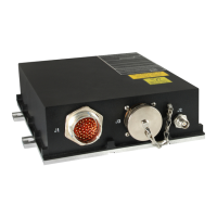
CMA-5024 GLSSU
This document includes Proprietary Information and shall not be reproduced or communicated to third party
without prior written permission by CMC Electronics Inc.
Page 118
November 21, 2008
B. GPS/SBAS Antenna Inspection
(1) Check antenna for dents, scratches, or other external damage; also check that it is free of foreign
material.
(2) Check aircraft interwiring co-axial antenna cable connector for damage, dents or loose hardware
and/or for insulation damage, bent or loose pins.
9. INSTALLATION
Note: Installation items required are listed in the table below.
INSTALLATION ITEMS PART NUMBER APPLICATION
Cable Assembly N/A GLSSU to aircraft systems; provided by
system integrator and installer
Cable connector, electrical,
41 contacts female
M83723/77R2041 N
CMC 230-990140-694
Clamp Strain Relief, straight M85049/52-1-20N
CMC 702-990140-693
Clamp Strain Relief 90°
(optional)
M85049/51-20N
CMC 702-990127-179
Mates the male chassis connector J1 on
the GLSSU
Cable connector, electrical,
100 contacts female
MS27473E22F35S Mates the male chassis connector J3 on
the GLSSU. The connector kit comes
complete with a straight cable clamp
Four No. 10-32 Capscrews Commercially available GLSSU mounting
Four No. 10-100°, FHMS screws Commercially available Antenna mounting
Active antenna, DO-301
compliant
N/A Antenna
O-ring for active antenna MS28775-142 Antenna mounting
A. Antenna Cable Layout and Routing Recommendations
When retrofitting the GLSSU in an existing antenna installation, carefully inspect the antenna cabling,
RF connectors and RF mounting hardware for damage, evidence of stress and wear.
Good design practices should be observed when routing the cable in the fuselage to minimize adverse
environmental conditions and stress, and to avoid physical damage such as mechanical abrasion and
chafing, for example by liberal use of conduits, tie-wraps and grommets.
Maintain good impedance matching all along the antenna cable and avoid impedance discontinuities
due to tight bends, abuses and mechanical stresses, including those inflicted in rough handling and
routing the cable during installation. If the antenna cable must be cut or extensions added, use only 50
Ohms coaxial RF connectors, adapters and coupling hardware intended for the type of RF cables at
hand. Account for their insertion losses.
Avoid long runs of the antenna cable alongside with other cables; special care must be taken to avoid
cross-coupling with cables carrying high power RF signal. Instead run it away from or across other
cables. Use coaxial cables with double-braid or triple-braid shields to minimize RF cross-coupling.
Do not route the antenna cable through multi-pin pressure bulkhead connectors, since this will cause
severe impedance mismatches and RF cross-coupling. Rather use a pressure bung.
B. GPS Antenna Installation
(1) Drill the necessary holes for the mounting screws using the mounting information (dimensions)
provided by the GPS Antenna manufacturer.
The document reference is online, please check the correspondence between the online documentation and the printed version.

 Loading...