INSTALLATION MANUAL
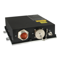
CMA-5024 GLSSU
This document includes Proprietary Information and shall not be reproduced or communicated to third party
without prior written permission by CMC Electronics Inc.
Page 101
November 21, 2008
SECTION II
INSTALLATION
1. GENERAL
The installation of a GLSSU in an aircraft requires the approval of the civil aviation certification agency
responsible for issuing the aircraft certificate of airworthiness.
Contact with the appropriate government authority prior to the installation and during the system planning is
highly recommended in order to minimize approval problems. If installation assistance is required, contact
CMC's Avionics Field Engineering Department at the telephone/telex/FAX numbers on the title page of this
manual.
The GLSSU does not need to be calibrated and no regular maintenance is required. The GLSSU envelope
drawing is shown in Figure 104 and its connectors pin-out are shown in Figure 105.
2. SYSTEM PLANNING
System planning is essential if the GLSSU is to be correctly interfaced with other aircraft subsystems and
instrumentation. For this purpose, refer to the antenna data, the pin assignments and the installation
instructions contained in this section. For the APD parameter descriptions and the available APD Files and
APD Configurations, refer to the Appendix E.
The location of the GLSSU and of its GPS/SBAS antenna varies with the type of aircraft in which it is
installed. The use of an active antenna allows long cable runs and flexibility in installation. As for any avionic
equipment, if at all possible, the GLSSU should be installed in a pressurized and temperature controlled
area with low levels of humidity and moisture in order to reduce environmental stresses. However, if
necessary, it can be installed in an unpressurized non-temperature controlled location. A typical antenna
location is shown in the Figure 101.
.
Figure 101. Typical Antenna Location
The document reference is online, please check the correspondence between the online documentation and the printed version.

 Loading...