INSTALLATION MANUAL
CMA-5024 GLSSU
This document includes Proprietary Information and shall not be reproduced or communicated to third party
without prior written permission by CMC Electronics Inc.
Page 114
November 21, 2008
If used, the HIS power input lines and circuit breakers should be independent from the ones used for the
main 28 VDC GLSSU power inputs (at connector pins J1-34 and j1-35), in order to avoid single points of
failure and to preserve redundancy. However, the 28 VDC power source should be common in order to
prevent nuisance warning messages; refer to the HIS Input Power APD parameter in Appendix E.
All ARINC 429 serial data busses must use twisted-shielded cables, and the cable shields must be
grounded at both ends. The nominal source impedance for the ARINC-429 bus drivers is 75 Ohms
(line-to-line).
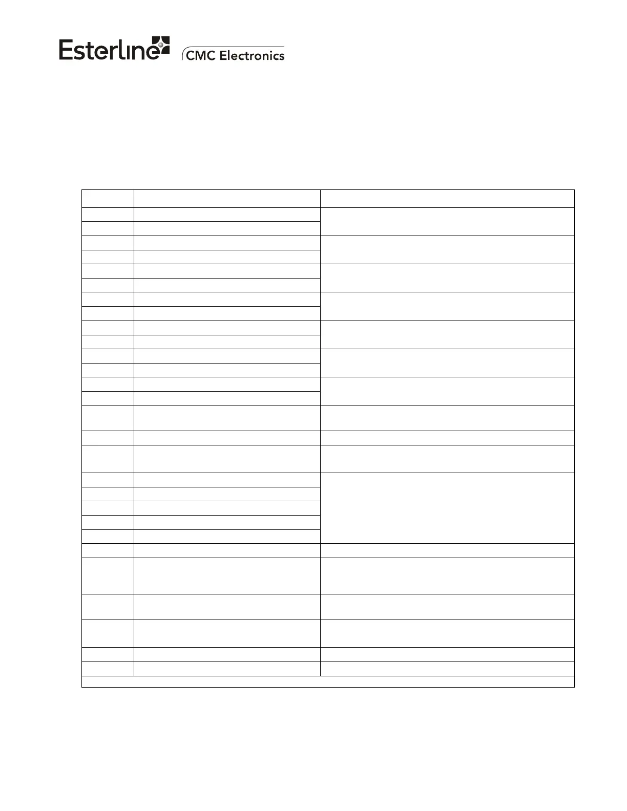
(J3) PIN SIGNAL NAME DESCRIPTION (FOR REFERENCE)
54 429 GLS/GPS #1 Out HI
55 429 GLS/GPS #1 Out LO
ARINC 429 data output; may be configured as a GPS
bus or a GLS bus
56 429 GLS/GPS #2 Out HI
57 429 GLS/GPS #2 Out LO
ARINC 429 data output; may be configured as a GPS
bus or a GLS bus
58 429 GLS/GPS #3 Out HI
59 429 GLS/GPS #3 Out LO
ARINC 429 data output; may be configured as a GPS
bus or a GLS bus
60 429 In Freq/Function Data Source HI
61 429 In Freq/Function Data Source LO
ARINC 429 data input from a Controller Unit
(optional))
64 429 In X-Talk #1 HI
65 429 In X-Talk #1 LO
ARINC 429 data input for GLSSU interconnection
(optional)
67 429 In X-Talk #2 HI
68 429 In X-Talk #2 LO
ARINC 429 data input for GLSSU interconnection
(optional)
62 429 spare input bus HI
63 429 spare input bus LO
ARINC 429 data Input
11 Functional/Guidance Test Discrete
Input
Open = Normal state. Grounded = Test request
12 N/A (Do not connect) Spare remote Discrete Input
13 Tune/Guidance Test Inhibit Discrete
Input
Ground = Inhibit test requests from pin 11.
Open = Allow test requests from pin 11.
14 APD #1 Select Discrete Input (LSB)
15 APD #2 Select Discrete Input
45 APD #3 Select Discrete Input
66 APD #4 Select Discrete Input (MSB)
16 APD Select Parity
Local Discrete Inputs for selecting the APD
Configuration; binary coding, odd parity check. Refer
to Appendix A
Open = logical 0, ground = logical 1.
17 Input Discrete Return Discrete Input ground
6 Approach Available Discrete Output * Ground = Pin 7 is closed to ground and the Five-
Minute Look-Ahead SBAS Integrity limits are below
the alert limits. Opened otherwise.
7 Approach Tuned Discrete Output * Ground = A valid approach is selected; opened
otherwise
8 System Valid Discrete Output * Ground = Normal operation;
Open = The GLSSU is non operational (Fault mode)
9 Discrete Output Return Discrete Output (GND) for pins 6, 7, 8
10 Discrete Output Return Discrete Output (GND) for pins 6, 7, 8
* Contact closure to ground; rating: 280 mADC (closed) & 36 VDC (open) maximum
Figure 108. Pin Assignments for J3; ARINC-429 Data and Discrete Interfaces
The document reference is online, please check the correspondence between the online documentation and the printed version.

 Loading...