INSTALLATION MANUAL
CMA-5024 GLSSU
This document includes Proprietary Information and shall not be reproduced or communicated to third party
without prior written permission by CMC Electronics Inc.
Page 103
November 21, 2008
3. ANTENNA INSTALLATION DATA
A. GPS/SBAS Antenna Characteristics
This must be an active antenna, meeting the requirements of a standard TSO C-190 as summarized for
reference below (extracted from RTCA/DO-301). If the aircraft operation is limited to class 1 as defined
in section I.2.A, use of an RTCA/DO-228 Change 1 compliant active antenna is acceptable. The
nominal RF output impedance is 50 Ohms. The characteristics apply over the full temperature range. In
addition:
(1) The DC power consumption of the antenna preamplifier must be greater that 15 mADC, in order
that the BIT circuits detect correctly the presence of the antenna.
(2) The antenna manufacturer must specify the nominal gain of the antenna preamplifier and the actual
gain variations of this value over the range of operating conditions and with time; a typical tolerance
is ±3 dB.
For an RTCA/DO-228 Change 1 active antenna, the following additional characteristics must be met:
(3) The antenna preamplifier must be compatible with the GLSSU power source at connector J2 is +9
VDC 20%.
(4) The DC power consumption of the antenna preamplifier must not exceed 60 mADC.
(5) The load capacitance on the output connector center conductor from the preamplifier DC power
interface circuitry must not exceed 0.75 uF.
(6) The preamplifier Noise Figure must not exceed 3.85 dB.
Known compatible RTCA/DO-228 Change 1 active antenna include the Sensor System S67-1575-132
and -133, and the AeroAntenna Technology AT575-143W-TNCF-000-RG-29.5-NM.
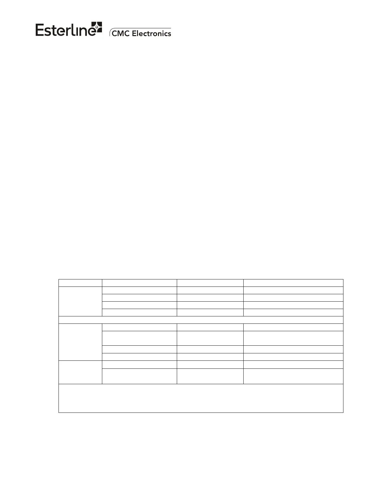
DEVICE PARAMETER REQUIREMENT CONDITION
Maximum gain +4 dBic Any satellite elevation angle
Minimum gain -5.5 dBic Elevation angles ≥ 5 °
Polarization Circular, RHCP
Passive
antenna
sensor
Axial ratio at boresight 3 dB maximum
Preamplifier gain 26.5 dB minimum Over 1575.42 ±2 MHz
DC Power input, integral
to coaxial cable input**
4.5 to 14.4 VDC
60 mA; ≤0.75 uF
Positive supply: Inner cable wire
Negative/return: Outer cable shield
Output impedance VSWR < 1.5:1 (dry)
Over 1575.42 ± 10.23 MHz
Antenna
Pre-amplifier
Preamplifier output power +20 dBm maximum*
Minimum boresight gain 29.5 dBic
Over 1575.42 ± 2 MHz
Active
antenna
G/T ratio for elevation
angles ≥ 5 °
-32.6 dB/K minimum
-31.6 dB/K minimum
Over 1575.42 ± 8 MHz
Over 1575.42 ± 2 MHz
* The RF circuits in the GLSSU may be damaged or burnout if its RF input power exceeds +20 dBm at
the GLSSU RF input, such as during transient overload conditions.
** The GLSSU power source at connector J2 is +9 VDC ±20% and the minimum external load current
must be 15 mADC. The external load current must not exceed 60 mADC.
Figure 102 gives the outline of a typical antenna. Typically the antenna will be installed and sealed
using an O-ring as illustrated.
The document reference is online, please check the correspondence between the online documentation and the printed version.

 Loading...