INSTALLATION MANUAL
CMA-5024 GLSSU
This document includes Proprietary Information and shall not be reproduced or communicated to third party
without prior written permission by CMC Electronics Inc.
Page E.15
November 21, 2008
When Off, the GPS Height label 370 is not output on the GLS/GPS ARINC 429 outputs of
type “GPS bus”.
Outputs of type “GLS bus” always transmit the GPS Height label.
This setting is selected to match the capability of the user of the bus data. It exists to support
legacy equipment designed before label 370 was defined as a standard in the ARINC 743A-
4 characteristic.
(19) GPS Only Measurement Block
When On, the Measurement block only includes GPS satellite data. When Off, both SBAS
and GPS data may be provided.
This setting is selected to match the capability of the user of the measurement block data.
Select On unless all connected equipment that uses the ARINC 429 measurement block
data can accept SBAS measurements.
(20) Air/Ground Indicator Type
When On, the Air/Ground Indicator (label 352 bit 29) is set to the Power Interruption
Air/Ground Status.
When Off, the Air/Ground Indicator (label 352 bit 29) is set to the Air/Ground State.
Since this is not part of ARINC 743A-4, most installations will not use this indicator. When
On, the indicator is based on ground speed only and will give report On Ground for a
hovering helicopter. Its advantage is its independence from the Air/Ground discrete input
when this input is not connected. When a weight on wheels or other On ground source is
available to drive the Air/Ground discrete, the Off setting is recommended. Note that in the
Off setting, this bit has the same value as the Test Inhibit bit of the GNSS Fault Summary
(label 355 bit 28).
B. Aircraft Personality Data (Numerical Parameters)
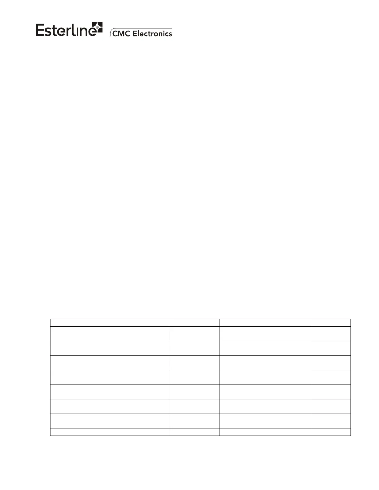
This section describes the APD parameters that are in the form of numerical parameters. The
table below provides a summary of the parameters; details are given in the sub-sections.
PARAMETER EXAMPLE* RANGE / RESOLUTION Units*
Left Navigation Center Lever Arm
Coefficients (X, Y, Z Components)
(0.00, 0.50,
-3.15)
±327.67 / 0.01 meter 0.01 m
Right Navigation Center Lever Arm
Coefficients (X, Y, Z Components)
(0.00, 0.00,
-3.15)
±327.67 / 0.01 meter 0.01 m
Center Navigation Center Lever Arm
Coefficients (X, Y, Z Components)
(0.00, -0.50,
-3.15)
±327.67 / 0.01 meter 0.01 m
Default Aircraft Pitch 2.0 ±45.0 / 0.1 degree;
positive = nose up
0.1 deg
Minimum Ground Speed for Track Angle
Output
7.0 +0.2 to +200.0 / 0.2 knot 0.1 Kt
Horizontal Cross-Check Minimum HIL
(HIL
Min
)
2.0 +50.0 / 0.1 meter 0.1 m
Vertical Cross-Check Minimum VIL
(VIL
Min
)
2.0 +50.0 / 0.1 meter 0.1 m
Horizontal SBAS Selection Threshold 40 +500 / 1 meter 1 m
The document reference is online, please check the correspondence between the online documentation and the printed version.

 Loading...