INSTALLATION MANUAL
CMA-5024 GLSSU
This document includes Proprietary Information and shall not be reproduced or communicated to third party
without prior written permission by CMC Electronics Inc.
Page 113
November 21, 2008
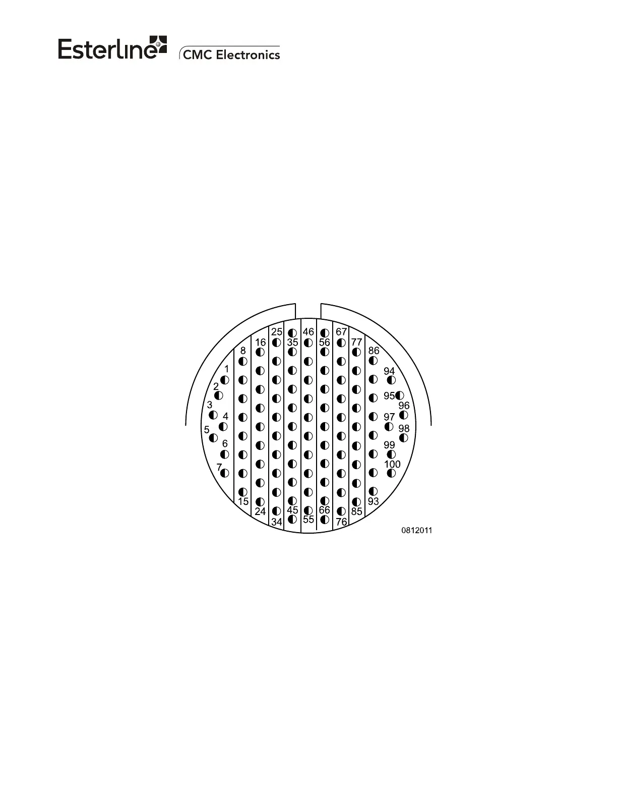
B. GLSSU APPROACH AIRCRAFT CONNECTOR J3
The connector pin number and location for the 100 pins of the 'J3' male connector are shown in Figure
107 as seen from the front of the GLSSU. It is intended to mate with a female cable connector type
MS27473E22F35S. The current rating of each contact is 5 ADC. The recommended wire gauge for the
installation is 22 AWG except where otherwise stated.
The connector pin number and location for the 100 pins of the 'J3' male connector are shown in Figure
108 as seen from the front of the GLSSU. It is intended to mate with a female cable connector type
MS27473E22F35S. The current rating of each contact is 5 ADC.
If installed, the recommended wire gauge for the optional HIS DC power input lines at pins J3-1 J3-2 is
22 AWG or larger, each wire will carry currents up to 1.5 A and must provide a maximum resistance of
1/3 Ohms to keep the overall cable voltage drop under 1 Volt.
Except where otherwise stated, the recommended wire gauge for the installation is 22 AWG, each wire
will carry currents up to 0.1 A and must provide a maximum resistance of 2 Ohms.
Use multistrand wires with at least 19 strands per wire.
(Seen from engaging face) Mates with connector plug MS27473E22F35S
Figure 107. GLSSU approach aircraft connector J3 (seen from the front of the GLSSU)
Figure 108, Figure 109 and Figure 110 provide pin assignments and system interwiring information.
Refer to Appendix A for a detailed signal description. The pins labeled "N/A" may be connected
internally hence they must be left unconnected as shown.
If the HIS device in the GLSSU is used, a circuit breaker rated at 1.5 A minimum should protect the
auxiliary +28 VDC HIS power input line at J3-1. The HIS power input (at pins J3-1 & J3-2) is DC-
isolated from the chassis ground and will withstand accidental polarity reversals without damage.
The document reference is online, please check the correspondence between the online documentation and the printed version.

 Loading...