INSTALLATION MANUAL
CMA-5024 GLSSU
This document includes Proprietary Information and shall not be reproduced or communicated to third party
without prior written permission by CMC Electronics Inc.
Page 110
November 21, 2008
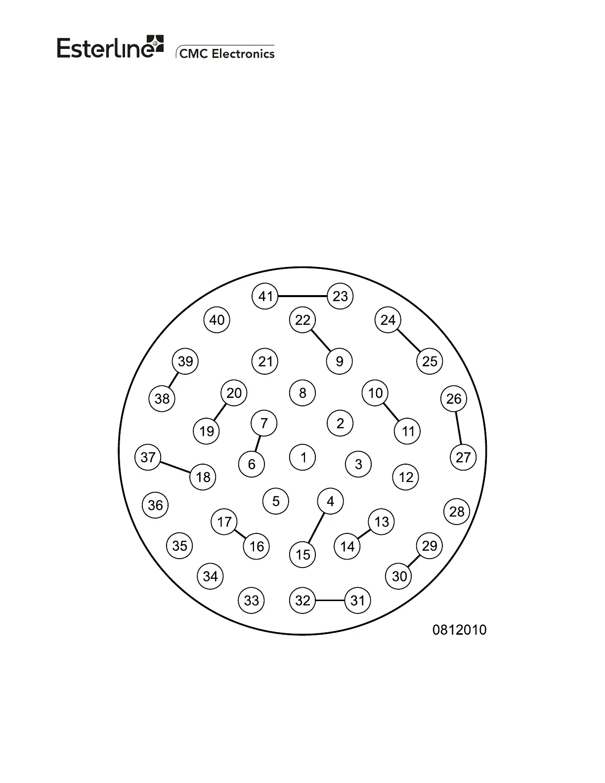
6. CONNECTOR PIN ASSIGNMENTS AND INTERWIRING
A. GLSSU NAVIGATION AIRCRAFT CONNECTOR J1
Figure 105 gives the pinout of the 41 pins male J1 on the GLSSU, intended to mate with a female cable
connector type M83723/77R2041N. The current rating of each contact is 7.5A.
The recommended wire gauge for the DC power input lines at pins J1-34 J1-35 is 22 AWG or larger,
each wire will carry currents up to 2 A and must provide a maximum resistance of 1/4 Ohms to keep the
overall cable voltage drop under 1 Volt.
Except where stated otherwise, the recommended wire gauge for the installation is 22 AWG, each wire
will carry currents up to 0.1 A and must provide a maximum resistance of 2 Ohms.
Use multistrand wires with at least 19 strands per wire.
Figure 105. GLSSU J1 connector (seen from the front of the GLSSU)
The document reference is online, please check the correspondence between the online documentation and the printed version.

 Loading...