INSTALLATION MANUAL
CMA-5024 GLSSU
This document includes Proprietary Information and shall not be reproduced or communicated to third party
without prior written permission by CMC Electronics Inc.
Page E.5
November 21, 2008
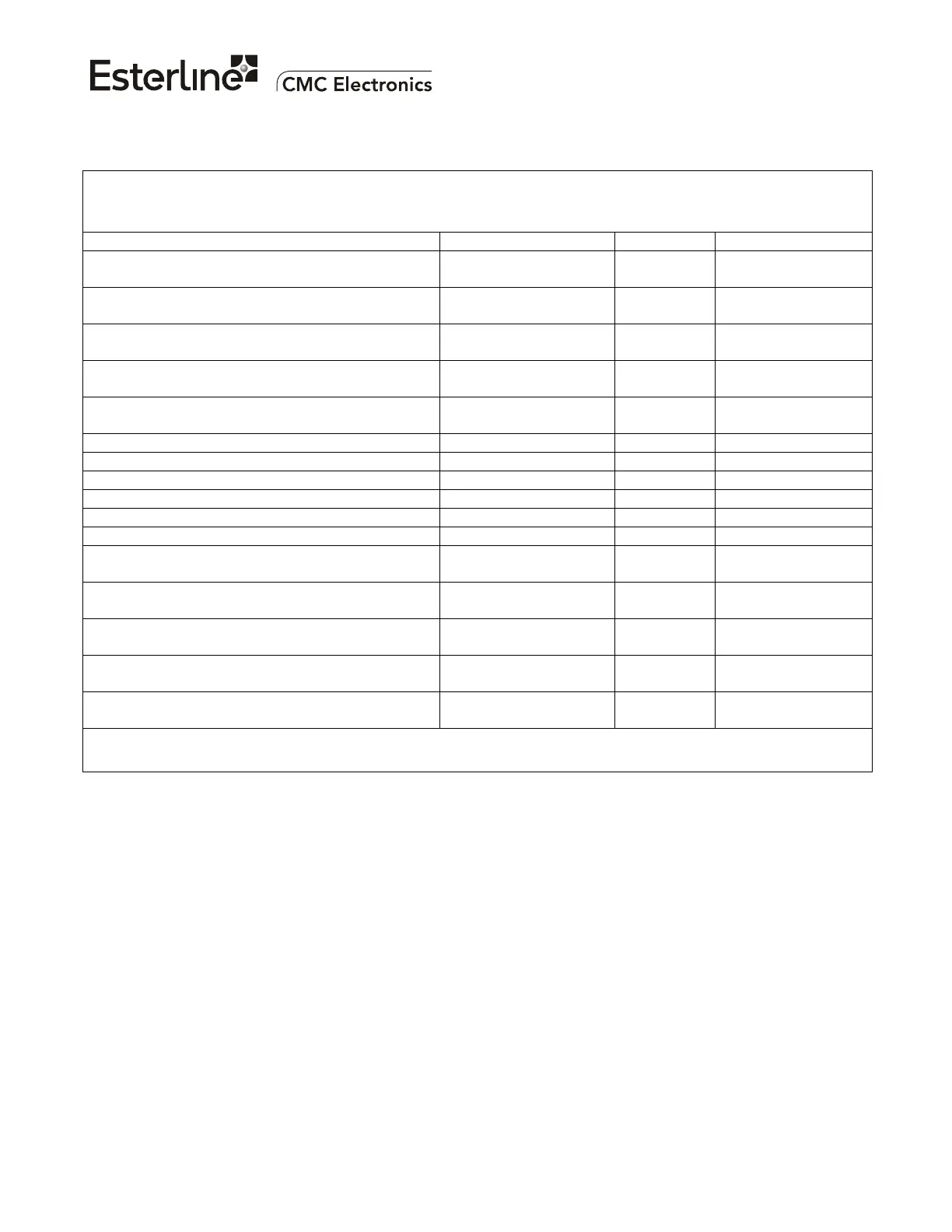
APD CID part number: 169-615462-XXX
APD Selection number: ______
Parameter Range / Resolution Value Notes
Left Navigation Center Lever Arm Coefficients (X,
Y, Z Components)
±327.67 /
0.01 meter
Units: 0.01 m
Right Navigation Center Lever Arm Coefficients
(X, Y, Z Components)
±327.67 /
0.01 meter
Units: 0.01 m
Center Navigation Center Lever Arm Coefficients
(X, Y, Z Components)
±327.67 /
0.01 meter
Units: 0.01 m
Default Aircraft Pitch ±45.0 / 0.1 degree
(positive = nose up)
Units: 0.1 deg
Minimum Ground Speed for Track Angle Output +0.2 to +200.0 /
0.1 knot
Units: 0.1 Kt
Horizontal Cross-Check Minimum HIL (HILMin) +50.0 / 0.1 meter Units: 0.1 m
Vertical Cross-Check Minimum VIL (VILMin) +50.0 / 0.1 meter Units: 0.1 m
Horizontal SBAS Selection Threshold +500 / 1 meter Units: 1 m
Vertical SBAS Selection Threshold +500 / 1 meter Units: 1 m
Approach Monitor Deactivation Threshold +4.00 / 0.01 nm Units: 0.01 m
SBAS PA Mode Range Limit +200 / 1 nm Units: 1 nm
GPS Bus Equipment ID +FFF /
1 hexadecimal
GLS Bus Equipment ID +FFF /
1 hexadecimal
GLS/GPS ARINC 429 Output #1 Bus Type 1 = GPS to 2 = GLS /
1 integer
GLS/GPS ARINC 429 Output #2 Bus Type 1 = GPS to 2 = GLS /
1 integer
GLS/GPS ARINC 429 Output #3 Bus Type 1 = GPS to 2 = GLS /
1 integer
Table 2 - GPS Sensor Aircraft Personality Data (Numerical Parameters)
For GPS Sensor Part Number 100-601967-XXX
The document reference is online, please check the correspondence between the online documentation and the printed version.

 Loading...