INSTALLATION MANUAL
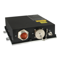
CMA-5024 GLSSU
This document includes Proprietary Information and shall not be reproduced or communicated to third party
without prior written permission by CMC Electronics Inc.
Page TC-2
November 21, 2008
1. GENERAL...........................................................................................................................................201
2. TEST TOOLS AND AIRCRAFT SYSTEMS INFORMATION.............................................................201
3. POST INSTALLATION INSPECTION ................................................................................................201
A. GPS/SBAS antenna inspection....................................................................................................201
B. GLSSU inspection ........................................................................................................................201
C. GLSSU Checks ............................................................................................................................202
4. OPERATIONAL GROUND TESTS.....................................................................................................205
A. Set-Up...........................................................................................................................................205
B. Check for system failures .............................................................................................................205
C. Check the GLSSU Navigation Mode............................................................................................205
D. Check the Navigation Data...........................................................................................................205
E. Check the Predictive RAIM...........................................................................................................206
F. Verify that the HIS passes-through the DME/ILS data.................................................................206
G. Verify that the auxiliary HIS power inputs are functional..............................................................206
5. ELECTROMAGNETIC COMPATIBILITY AND INTERFERENCE TESTS.........................................206
A. Test cycle / pass-fail criteria .........................................................................................................206
B. Set-up...........................................................................................................................................207
C. RF interference Tests...................................................................................................................208
D. Rotor blade interference test........................................................................................................209
SECTION IV REMOVAL...........................................................................................................................301
1. GENERAL...........................................................................................................................................301
A. GLSSU..........................................................................................................................................301
B. GPS Antenna................................................................................................................................301
SECTION V SERVICING ..........................................................................................................................401
SECTION VI CLEANING AND PAINTING...............................................................................................501
SECTION VII APPROVED REPAIRS.......................................................................................................601
APPENDIX A INTERFACE INFORMATION, GLSSU AIRCRAFT CONNECTOR SIDE (J1, J3)........... A.1
1. DISCRETE SIGNAL INTERFACES.................................................................................................. A.1
1.1 Discrete Inputs...............................................................................................................................A.1
1.1.1 ARINC 429 Source/Destination Identifier (SDI) Discrete inputs....................................................A.2
1.1.2 Air/Ground Discrete input..............................................................................................................A.2
1.1.3 Discrete Outputs............................................................................................................................A.4
1.2 ARINC 429 INTERFACES.............................................................................................................A.5
1.2.1 ARINC 419/429 Data Interface Structures ....................................................................................A.5
1.2.2 ARINC 429 inputs..........................................................................................................................A.6
1.2.3 ARINC 429 data inputs configuration............................................................................................A.6
1.2.4 ARINC 429 input data rates...........................................................................................................A.7
1.2.5 ARINC 429 input priority................................................................................................................A.7
1.2.6 ARINC 429 input data format ........................................................................................................A.7
1.2.7 SBAS Approach Selection data inputs....................................................................................... A.14
1.2.8 ILS/DME data concentrator interface ......................................................................................... A.14
1.2.9 ARINC 429 Outputs.................................................................................................................... A.15
1.2.10 ARINC 429 output Status/Sign matrix (SSM) bits processing.................................................... A.16
1.2.11 ARINC 429 output data format................................................................................................... A.16
1.2.12 Selected SBAS Approach outputs.............................................................................................. A.27
1.3 RS232/RS422 SERIAL BUSSES............................................................................................... A.28
1.3.1 RS232 bus designation .............................................................................................................. A.28
1.3.2 Time-Mark output busses........................................................................................................... A.28
APPENDIX B RESERVED........................................................................................................................ B.1
The document reference is online, please check the correspondence between the online documentation and the printed version.

 Loading...