I STANDING PILOT
BURNER
The standing pilot model furnaces have
one pilot burner. The burner has a
thermocouple to sense pilot flame and
to prevent the gas valve from opening if
the pilot light goes out.
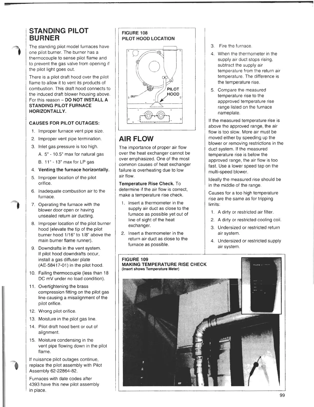
There is a pilot draft hood over the pilot
flame to allow it to vent its products of
combustion. This draft hood connects to
the induced draft blower housing above.
For this reason -
DO NOT INSTALL A
STANDING PILOT FURNACE
HORIZONTALL V.
CAUSES FOR PILOT OUTAGES:
1. Improper furnace vent pipe size.
2. Improper vent pipe termination.
3. Inlet gas pressure is too high.
A. 5" - 10.5" max for natural gas
B. 11" - 13" max for LP gas
4.
Venting the furnace horizontally.
5. Improper location of the pilot
orifice.
6.
Inadequate combustion air to the
furnace.
•
7. Operating the furnace with the
blower door open or having
unsealed return air ducting.
8.
Improper location of the pilot burner
hood (elevate the tip of the pilot
burner hood 1/16" to 1/8" above the
main burner flame runner).
9.
Downdrafts in the vent system.
If pilot hood downdrafts occur,
install a gas diffuser plate
(AE-58417-01) in the pilot hood.
10. Failing thermocouple (less than 18
DC mV under no load condition).
11. Overtightening the brass
compression fitting on the pilot gas
line causing a misalignment of the
pilot orifice.
12. Wrong pilot orifice.
13. Moisture in the pilot gas line.
14.
Pilot draft hood bent or out of
alignment.
15. Moisture condensing in the
vent pipe flowing down in the pilot
flame.
If nuisance pilot outages continue,
replace the pilot assembly with Pilot
Assembly 62-22864-82.
Furnaces with date codes after
4393 have this new pilot assembly
in place.
FIGURE 108
PILOT HOOD LOCATION
AIR FLOW
The importance of proper air flow
over the heat exchanger cannot be
over emphasized. One of the most
common causes of heat exchanger
failure is overheating due to low
air flow.
Temperature Rise Check. To
determine if the air flow is correct,
make a temperature rise check.
1. Insert a thermometer in the
supply air duct as close to the
furnace as possible yet out of
line of sight of the heat
exchanger.
2. Insert a thermometer in the
return air duct as close to the
furnace as possible.
3. Fire the furnace.
4. When the thermometer in the
supply air duct stops rising,
subtract the supply air
temperature from the return air
temperature. The difference is
the temperature rise.
5. Compare the measured
temperature rise to the
appproved temperature rise
range listed on the furnace
nameplate.
If the measured temperature rise is
above the approved range, the air
flow is too slow. More air must be
moved either by speeding up the
blower or removing restrictions in the
duct system. If the measured
temperature rise is below the
approved range, the air flow is too
fast. Use a lower speed tap on the
multi-speed blower.
Ideally the measured rise should be
in the middle of the range.
Causes for a too high temperature
rise are the same as for tripping
limits:
1. A dirty or restricted air filter.
2.
A dirty or restricted cooling coil.
3. Undersized or restricted return
air system.
4. Undersized or restricted supply
air system.
FIGURE 109
MAKING TEMPERATURE RISE CHECK
(Insert shows Temperature Meter)
99